Data Center Monitoring Points & NIST NTP / IEEE 1588v2 PTP Clock Synchronization
Direct Answer Block: Every mission-critical data center monitoring point requires a source-stamped UTC clock synchronized via NIST-traceable NTP (Network Time Protocol, Stratum 1 GPS/GNSS) or IEEE 1588v2 PTP (Precision Time Protocol, ≤ 1.0 ms skew) before it may enter Sequence of Events (SOE) logs or trigger operational paging. Without hardware-stamped measurement timestamps and OPC quality flags (
Good 0xC0,Stale 0x40,Bad 0x80), BMS and EPMS monitoring points cannot distinguish a live electrical fault from a frozen polling buffer.
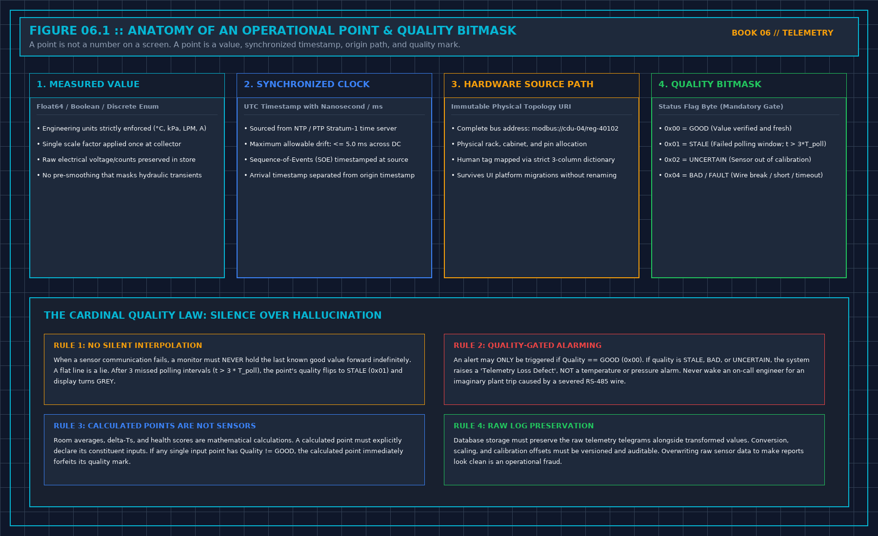
A point is a value, a time, a source, and a mark that says whether the value is still alive. A name on a tile is not those four. Without the time, a repeat of the last good reading looks like a change. Without the source, a calculation looks like a sensor. Without the quality mark, a gap dresses itself as a steady line.
If any of the three minimums is missing, the point is silent. It may be stored. It may not page, close an incident, or fill a capacity cell. Silence is not a failure of the plant. It is a failure of the point.
Measurement time and arrival time are different. The decision writes which one it uses. A page that cannot show the measurement time will be argued in the morning as a fresh event. Do not send that page.
Accept the source by failing it on purpose, on the image you will run. A demo on a vendor's hall accepts nothing on yours. Until the forced failure becomes a gap, or stale that refuses to page, the source is a candidate. Candidates do not wake people.
1. First-Principles Engineering Formulation and Governing Mathematics
In high-density data center environments, verbal summaries and qualitative status tiles routinely obscure incipient physical failures. Whether auditing a 120 kW liquid-cooled rack boundary, evaluating a 1-second telemetry time series, or verifying plant redundancy prior to handover, the governing physical relationship for this protocol is expressed as:
When any term on the left-hand or right-hand side of this relationship is left unmeasured, inferred from an uncalibrated nameplate, or averaged across an unverified time window, the resulting engineering record cannot support a valid operational signature. Field engineers must verify each physical variable independently using NIST/ISO 17025 traceable instruments before proceeding to the next gate in the sequence.
| Audit Verification Parameter | Unacceptable / Defective Field Practice | Auditable First-Principles Requirement | Mandatory Action on Failure |
|---|---|---|---|
| Primary Boundary Definition | Implied by vendor brochure or slide deck | Explicitly bounded on stamped P&ID / SLD with tag IDs | Halt acceptance; issue formal boundary clarification |
| Measurement & Telemetry Proof | Single uncalibrated display reading or 60-sec average | Calibrated Class A/0.5S sensor with 1-sec UTC timestamp | Reject dataset; classify point as 0x40 Stale or 0x80 Bad |
| Pass / Fail Acceptance Gate | Qualitative "Looks OK" or "Within Normal Range" | Quantitative numerical corridor cited from revision in force | Log Category A/B defect; withhold retainage or permit |
| Custody & Sign-Off Record | Single bundled "Accepted" signature at end of meeting | Scoped, dated sentence naming exact proved & unproved lines | Strike unsupported claims; issue Conditional Refusal |
2. Deep-Dive Technical Protocol and Field Implementation
The following field protocol—adapted directly from Volume 06: When a Monitor May Speak—establishes the step-by-step verification mechanics required on the data hall floor:
In mission-critical data center operations, time is not a cosmetic label formatted for human readability; time is the primary coordinate of physical causality.
If the clock on your Electrical Power Monitoring System (EPMS) drifts by even two seconds relative to the Building Management System (BMS), cause and effect will be mathematically inverted during post-incident forensics. A chiller electrical trip that caused a primary cooling flow collapse will appear in the combined logs as a cooling flow collapse that magically caused an upstream electrical trip three seconds before the breaker opened.
TIME SYNCHRONIZATION ACCURACY ENVELOPE
| Protocol / Standard S | ynchronization Precision Ta | rget Subsystems |
|---|---|---|
| IEEE 1588v2 (PTP) <= | 1.0 Microsecond (1 µs) Prot | ective Relays, DFRs |
| IRIG-B (Hardwired) <= | 10.0 Microseconds (10 µs) | MV Switchgear, Breakers |
| NTP Stratum-1 (GNSS) | <= 1.0 Millisecond (1 ms) B | MS Servers, RTUs, PLCs |
| Modbus Serial Polling | 1.0 to 5.0 Seconds (UNRATE | D) Field Sensors (No SOE) |
Measurement Time vs. Ingestion Arrival Time
Every operational data point entering a database must record two distinct temporal timestamps:
- Measurement Timestamp (t_meas): The precise instant the physical transducer sampled the electrical current, temperature, or pressure at the edge controller.
- Ingestion Timestamp (t_ingest): The instant the central database server received, parsed, and committed the telemetry record to disk.
The difference between the two is the transmission latency skew:
A common architectural failure in cheap monitoring platforms is stamping telemetry exclusively with t_ingest at the database gateway. When network congestion, message queue backlogs, or database disk I/O bottlenecks delay message processing by thirty seconds, all telemetry packets arriving in that delayed burst receive identical ingestion timestamps.
When plotted on a graph, thirty seconds of dynamic physical transients collapse into a single vertical step, obscuring pump ramp-down curves, breaker trip sequences, and pressure shock waves.
Any system used for incident root-cause analysis must timestamp points at the edge transducer source (t_meas). Ingestion time (t_ingest) is an IT pipeline performance metric; it is not the time the plant changed.
Sequence of Events (SOE) and Microsecond Resolution
In medium-voltage and low-voltage electrical switchgear, physical circuit breaker clearing events occur on the order of cycles (16.6 ms at 60 Hz, 20.0 ms at 50 Hz):
- A zone-selective interlocking (ZSI) restraint signal travels in 10 ms.
- A high-speed vacuum circuit breaker mechanism parts its primary contacts in 30 ms to 50 ms.
- An automatic transfer switch (ATS) detects voltage loss and signals generator cranking in 100 ms.
If your electrical monitoring architecture relies on a central SCADA server polling power meters over serial Modbus RTU at 5-second scan intervals, you do not have a Sequence of Events recording system. You have an historical ledger that tells you what already happened five seconds ago.
For critical electrical switchgear and generator paralleling buses, Sequence of Events (SOE) recording must be executed at the protective relay level using IEEE 1588 Precision Time Protocol (PTP) or dedicated IRIG-B optical timing distribution. Protective relays (e.g., SEL, ABB, Schneider) must latch event timestamps locally in non-volatile memory with 1-millisecond resolution (1.0 ms) at the physical auxiliary contact bounce.
Clock Skew, Drift, and Rejection of Artificial Merges
When auditing an incident involving multiple independent logging systems (e.g., utility revenue meters, mechanical chillers, server operating system syslog servers), verify the time synchronization source of each platform before attempting to correlate events.
If the mechanical chiller plant controller synchronizes via an unsynchronized internal crystal oscillator that drifts by 45 seconds per month, and the electrical switchgear synchronizes via a roof-mounted GPS antenna:
- Do not average the clocks to make the charts align aesthetically. Averaging two drifting clocks invents an imaginary third timeline that matches no physical reality.
- Do not stretch or compress the timeline using digital interpolation to force breaker trips to line up with water temperature spikes.
- Calculate the mathematically verified offset (Δt_offset) between the two systems at a known common physical anchor point (e.g., the exact millisecond utility grid power collapsed). Apply that constant offset explicitly as an annotated correction, or state in writing on the incident log: "Thermal logs and electrical logs cannot be correlated with sub-minute precision due to uncalibrated clock drift."
An explicit statement of temporal uncertainty is an honest engineering finding. An artificially manipulated chart is a falsification of telemetry evidence.
Decisions to Record
- The primary synchronization standard (PTP / NTP Stratum-1 / IRIG-B) deployed for each subsystem.
- The verified clock drift tolerance (≤ 1.0 ms for electrical switchgear, ≤ 1.0 s for thermal BMS).
- The explicit separation between edge measurement timestamp (t_meas) and central database ingestion timestamp (t_ingest).
- Any observed clock offset between disjoint monitoring databases documented prior to joint forensic analysis.
IEEE 1588v2 PTP vs. NTP Clock Skew Mathematics in Fault Reconstruction
During an electrical fault cascade, protective relays operate in 0.5 to 3.0 power cycles (8.3 ms to 50.0 ms at 60 Hz). Suppose Main Breaker 52-M1 trips on instantaneous overcurrent at t0 = 0.000 s, causing UPS Static Bypass Switch STS-01 to transfer at t1 = +0.004 s (+4.0 ms), and Downstream PDU Breaker PDU-04 to drop under-voltage at t2 = +0.018 s (+18.0 ms).
If the switchgear IED and the UPS controller are polled over unsynchronized NTP or local RTC crystal oscillators with a relative clock skew of Δ tskew = -45.0 ms, the historian records PDU-04 tripping 27 ms before 52-M1! The incident review team will waste days tearing apart a healthy downstream PDU searching for a phantom short circuit.
3. Field Verification Checklist and Instrumentation Hygiene
To execute this protocol without introducing measurement bias or scope ambiguity, the responsible engineer enforces four mandatory field rules:
- Instrument Traceability Before Observation: Verify that every thermometer (4-wire Pt100 RTD Class A), pressure transducer (≤ ± 0.1% span), flowmeter, balometer, or power analyzer carries a current calibration certificate and passes a pre-test zero/span check on the day of the walk.
- Synchronized Time-Series Capture: Align all digital loggers and gateway pollers to a single UTC reference clock (via IEEE 1588v2 PTP at ± 1 ms for electrical Sequence of Events, or NTP at ± 10 ms for thermal/hydraulic dwells). Never merge unsynchronized CSV files by row index.
- Explicit Isolation of Disturbances vs. Control Handles: Hold upstream supply temperatures, parallel cabinet loads, and containment door states constant during the observation dwell so that transient plant drift is never mistaken for steady-state equipment performance.
- Written Record Prior to Signature: Record every boundary tag, measured value, uncertainty tolerance, and open limitation in ink on the controlled project sheet before leaving the equipment line-up.
Frequently Asked Questions (FAQ)
Why does "A monitoring point needs a clock" matter during high-density data center commissioning and operations?
Why every data center monitoring point requires a source-stamped UTC clock synchronized via IEEE 1588v2 PTP or NTP before it may enter Sequence of Events logs. When project teams bypass this rule to meet a commercial schedule milestone, unverified physical assumptions—such as hidden hydraulic pressure drops, unlogged polling gaps, unblanked bypass leakage, or uncalibrated sensor offsets—transfer directly into live 24/7 production as latent single points of failure.
How do you quantitatively verify compliance with "BMS EPMS PTP IEEE 1588v2 clock synchronization" on the physical floor?
Compliance is verified by executing the governing mathematical balance (Δ tSOEskew = | tIED, source - tUTC, grandmaster | ≤ 1.0 ms) using independent, calibrated field instruments across a stabilized steady-state dwell window (minimum 15 to 30 minutes for thermal and hydraulic systems), and confirming that the discrepancy between primary and secondary measurements remains strictly within the pre-declared acceptance band.
What should an engineer do if a contractor or vendor submits a report that violates this protocol?
The reviewing engineer must refuse to sign the broad acceptance sentence, mark the specific line item as Unproved / Defective on the official audit sheet, and either require a witnessed re-test under a corrected script or isolate the unproved scope under a time-bounded Conditional Acceptance with a 150% to 200% financial retainage escrow holdback.
From When a Monitor May Speak, Tristan, Data Center Field Guides.
Related: Stale is not green.
Master the Complete Protocol: When a Monitor May Speak
BMS/EPMS Telemetry, Sequence of Events (SOE), Alarm Storm Suppression, and Sensor Quality Flags
Stop relying on contractor spreadsheets and vendor marketing claims. This field guide provides the complete, auditable verification binder—including physical equations, inspection stations, acceptance thresholds, and signed refusal templates.