A liquid load bank is not a CDU: First-Principles Data Center Engineering Protocol
Direct Answer Block: Why a rack-side liquid load bank is a thermal and hydraulic stand-in for an NVL72 rack—never a substitute for the facility Coolant Distribution Unit (CDU). In mission-critical data center commissioning and operations, engineers enforce this boundary using deterministic physical equations, calibrated field instrumentation, and auditable sign-off gates rather than relying on vendor brochure summaries, uncalibrated software plots, or verbal assurances. Every measurement and state transition must be recorded with synchronized UTC timestamps and explicit pass/fail thresholds before a signature is granted.
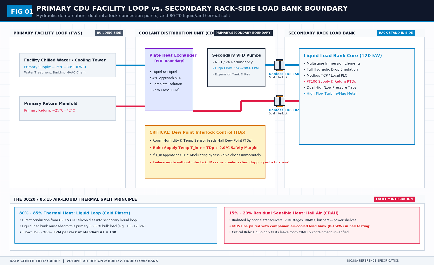
A liquid load bank puts heat and flow where the rack will later put heat and flow. That is the job. It is not a coolant distribution unit, and it is not a proof that the IT equipment will boot.
Teams blur those jobs because the pipes look similar. The bank rejects heat the way a loaded rack rejects heat, so the hall-side loop can be run before the racks exist. The CDU is the plant that supplies that loop. If the bank is asked to "be the CDU for a day," the test no longer has a plant and a load. It has one box doing both, and a pass that will not survive the day the real CDU is connected.
The same split applies to the IT. A stable supply temperature at the bank does not mean a GPU tray will train. Boot, optics, and job health are a different sentence. Write that limit on the requirements sheet before anyone cuts metal. A sheet that says "represents the rack" without saying what it does not represent will be quoted as a full-hall proof.
Interface numbers do not belong in a general article, and they do not belong in the book. The specification then in force is cited on your own sheet. A marketing multiple for coolant flow is not that specification. If the only flow number in the room came from a slide, stop and get the document that actually governs the test.
1. First-Principles Engineering Formulation and Governing Mathematics
In high-density data center environments, verbal summaries and qualitative status tiles routinely obscure incipient physical failures. Whether auditing a 120 kW liquid-cooled rack boundary, evaluating a 1-second telemetry time series, or verifying plant redundancy prior to handover, the governing physical relationship for this protocol is expressed as:
When any term on the left-hand or right-hand side of this relationship is left unmeasured, inferred from an uncalibrated nameplate, or averaged across an unverified time window, the resulting engineering record cannot support a valid operational signature. Field engineers must verify each physical variable independently using NIST/ISO 17025 traceable instruments before proceeding to the next gate in the sequence.
| Audit Verification Parameter | Unacceptable / Defective Field Practice | Auditable First-Principles Requirement | Mandatory Action on Failure |
|---|---|---|---|
| Primary Boundary Definition | Implied by vendor brochure or slide deck | Explicitly bounded on stamped P&ID / SLD with tag IDs | Halt acceptance; issue formal boundary clarification |
| Measurement & Telemetry Proof | Single uncalibrated display reading or 60-sec average | Calibrated Class A/0.5S sensor with 1-sec UTC timestamp | Reject dataset; classify point as 0x40 Stale or 0x80 Bad |
| Pass / Fail Acceptance Gate | Qualitative "Looks OK" or "Within Normal Range" | Quantitative numerical corridor cited from revision in force | Log Category A/B defect; withhold retainage or permit |
| Custody & Sign-Off Record | Single bundled "Accepted" signature at end of meeting | Scoped, dated sentence naming exact proved & unproved lines | Strike unsupported claims; issue Conditional Refusal |
2. Deep-Dive Technical Protocol and Field Implementation
The following field protocol—adapted directly from Volume 01: Design and Build a Liquid Load Bank for NVL72 Racks—establishes the step-by-step verification mechanics required on the data hall floor:
The liquid path is where a confident heater becomes a prototype that cannot be hooked up, cannot be isolated, or cannot be believed. Heat can be added in more than one way. Liquid only goes where you left it a path, and it only stays there if the joints, the valves, and the hose routing were treated as the design rather than as plumbing to be figured out at the end.
This chapter is a set of choices. It is not a parts list. Fitting families, sizes, and materials callouts come from the specification then in force and from the coolant you actually have. What this chapter insists on is the job each choice does, the failure it is meant to prevent, and the acceptance check that proves you did not skip it.
Draw the boundary first
Before you sketch a pipe, draw the line where the load bank ends and the rest of the world begins. For this book, that line is the rack-side interface: the manifold, or the hose that mates to the manifold, depending on who owns the hose. The load bank does not include the CDU. It does not include the hall piping. It does not include a temporary bench loop, even if the prototype spends its first month bolted to one.
Write one sentence: “Delivered scope ends at X. The mating half of X is owned by Y.” If you cannot name X and Y, every later argument about a leak will be an argument about responsibility, which is a worse place to discover the boundary than a diagram.
Put the sentence on the one-line diagram. The diagram has boxes, arrows, and names. It does not have a site plan, a room number, or a vendor logo. It should be redrawable by a stranger from the prose in the delivery file. If it cannot be redrawn, it is a picture, not a diagram.
Name the streams. Supply into the load. Return out of the load. Any bypass that exists so flow can be trimmed without starving the CDU connection. Any drain or vent. If a stream does not have a name, someone will measure the wrong one and label it with the right word.
Primary side and secondary side
Liquid-cooling conversations mix two loops until everyone is nodding at different machines. Separate them in the first paragraph of your diagram notes.
One side is the heat-rejection side: the side that ultimately dumps heat, often through a CDU’s heat exchanger to some other liquid or to air. The other side is the rack side: the liquid that would have gone through the IT equipment, and that your load bank is pretending to be. The names “primary” and “secondary” are used differently by different vendors. Do not inherit a vendor’s habit without writing your own glossary line. Pick “CDU-side” and “rack-side” if the inherited words are already confused in your project. Consistency inside your file beats fidelity to a slide.
The load bank in this book sits on the rack side of that boundary. It presents heat and resistance to whatever is supplying rack-side liquid. It is not a substitute for the CDU’s heat exchanger, pumps, or controls. If your prototype has its own pump, say so, and say whether that pump is only for bench acceptance or part of the delivered stand-in. A pump that quietly becomes “the” flow source will make every flow reading in the shop unrepresentative of a rack that expects to be fed.
If the project also needs a load on the CDU-side loop, that is a different requirement line and usually a different machine. Do not stretch this unit across both sides because the purchase order had one line item. Two duties on one chassis, unlabeled, is how a valve meant for isolation becomes a valve that starves the wrong loop.
Write, under the diagram: which side this unit occupies, what feeds it, and what it is not allowed to replace. Three sentences. If you need a page, you have not drawn the boundary. You have started a system description, which belongs in the project book.
Isolation
Each external connection that can spill a loop needs a way to shut it off. A quick disconnect is a joint. It is sometimes also a valve. It is not, by itself, a maintenance plan. The first time you must remove a hose that is still full, you will learn whether you designed isolation or hoped for it.
Isolation has a place, a direction, and a visible state. Place: close enough to the point of spill that the trapped volume is small, and far enough from the joint that you can actually get a hand on it when the hose is fitted. Direction: you know which side stays live when it closes. Visible state: a person who did not build the unit can tell open from closed without a manual. If the state is invisible, acceptance treats it as unknown, and unknown is not open.
Two connections, supply and return, mean two independent isolation duties. A single shared valve drawn on a preliminary schematic without independent supply and return shutoffs cannot isolate the loop during hose disconnection; reject any schematic that omits dual-port isolation. Also isolate any spare port. A spare port without its own shutoff valve is an unisolated leak path.
Drains and vents are isolation problems in miniature. A drain that is a plug, with no valve and no captive cap, will be opened at the worst moment because it was the only way to empty the unit. A vent that cannot be closed will become an air leak or a spray. Write drain and vent as named devices with a closed state, or write that the unit is not meant to be drained except by breaking a joint, and accept that limitation in the file. The limitation is sometimes honest for a sealed module. It is rarely honest for a prototype you will service.
Acceptance for isolation is physical, not documentary. Close the valve. Confirm the downstream side can be opened without a continuous spill. Confirm the label matches the diagram. If you cannot do this without filling the entire hall loop, do it on the bench before the unit and the hall are inseparable. Gate 1 exists for this. Do not postpone it to a day when the loop is chemically treated and politically sensitive.
One in service, one spare
A single external fitting is a single point of delay and a single point of damage. The pattern worth stealing from real load-bank specifications is not a size. It is the pattern: one connection in service, one held as spare, same duty, able to be brought into service without redesigning the manifold on the truck.
Say what spare means, because the word is cheap.
A capped port on the unit manifold, same family as the live port, isolated, labeled, and reachable. This is the minimum that deserves the word.
A second hose already fitted and capped at the far end. More ready, more able to kink, more able to be mistaken for the live hose. If you choose this, labels and caps are acceptance items, not accessories.
A spare fitting in a bag in a drawer. That is a spare part. It is not a spare connection. Do not write it on the diagram as if it were plumbed.
The spare must see the same duty if it is placed in service: same isolation, same instrument story, or a written limitation that the spare path is uninstrumented and therefore only a recovery path, not a test path. People will test on the spare if the live port is damaged. If the spare has no flow meter and no temperatures, they will do it anyway and the record will lie. Either instrument the spare path or write, in large letters, that a test on the spare path is not a valid acceptance and not a valid stand-in.
Who may change from live to spare. On the day, the default is: nobody, unless the acceptance sheet names the person and the retest that follows. Changing ports changes the hydraulic path. A quiet swap is a different unit.
Hose workmanship
Soft hose is not a license to ignore routing. A hose that meets the fitting family and folds flat behind the chassis is a failed hose, even if it has never leaked. Kinks restrict flow, create a pressure drop you will blame on the rack, and fatigue the liner. Rub points wear through. A bend tighter than the hose can live with will look acceptable empty and wrong when pressurized.
Specify routing as a set of prohibitions and one positive statement. Prohibitions: no kink, no rub on an edge, no reliance on the connector to carry the hose’s weight, no loop that traps air at the high point you forgot, no run that blocks the module you said must come out. Positive statement: the hose length and path are fixed enough that two people will route it the same way. “Field fit” without a path is how every unit becomes a unique hydraulic accident.
Hose length is a design choice. Too short and the unit must sit in a place that conflicts with the rack. Too long and the spare loop becomes a heat exchanger and a trip hazard. Write a maximum unsupported length and a maximum total length as project numbers, or mark them unknown until the manifold location is known. Do not copy a length from another hall.
The elastomer, or metal, must be compatible with the coolant chemistry and with the maximum operating temperature the duty sheet allows. Name the material class (for example, peroxide-cured EPDM or PTFE-lined stainless braid) on the unit’s file and cite the exact coolant formulation. Do not reuse a catalog hose from a previous project and assume chemical compatibility across different fluids; inhibited propylene glycol (PG25), deionized water, and dielectric fluids attack different elastomers and seals. If the exact coolant formulation is not yet specified, the hose material cell remains unknown, and Gate 1 cannot close. Shipping a hose of unverified chemical compatibility is never an acceptable way to hold a schedule.
Clamps and ferrules are part of the hose, not part of the decoration. A joint that depends on a clamp must have the clamp visible and of the type the hose maker requires. Acceptance includes a look, not a tug that damages the joint. If the joint is a type that should not be tugged, write the check as visual and as a pressure test, not as heroics.
Air in the hose is a measurement problem as well as a flow problem. A high point without a vent will collect air, the pump will sound wrong, and the flow meter will read a mixture. Walk the routed hose and mark high points. Either vent them or route them out. This is a Gate 1 and Gate 3 issue. It is cheaper on Gate 1.
Interference
Static acceptance exists because drawings and chassis disagree in the real world. The check is practical. With hoses, valves, sensors, and connectors fitted, can a person reach every isolation device, close it, and remove a module without dismantling the loop. Can the unit sit at the distance from the manifold that the hose length assumes, without the enclosure striking the rack, the floor, or the door of the CDU. Does the display, if it has one, face the person who must read it, or does it face the wall the rendering never included.
Interference is not only metal-to-metal. It is hand-to-valve. A valve that meets the drawing and cannot be turned while the hose is on has failed. It is eye-to-label. A label that exists and cannot be read with the hose fitted has failed. It is tool-to-fastener. A module you said could be removed, which requires a driver that does not fit between the hose and the frame, has failed.
Do these checks empty, then again at pressure if the hose grows or stiffens when filled. Hoses change shape. A check done only on a CAD model is a wish. A check done only empty is incomplete. You do not need a hall to do the filled check. You need caps, a pump, and honesty.
Record interference as a list of reaches, not as “layout OK.” Reaches: supply isolation, return isolation, spare cap, drain, module release, power disconnect, alarm silence if it is local. Each is pass or fail. A narrative paragraph will hide the one reach that failed.
What fittings are for: Danfoss FD83 vs. blade-level couplings
You will be asked to pick a fitting early, usually by being shown whatever quick disconnect was left over from a previous server build. Refuse that inheritance. Pick the hydraulic job, understand the scale of the interface, and then let the specification name the family.
In data center liquid cooling commissioning, people often confuse two completely different connection tiers:
- Blade-level couplings (such as OCP UQD02/04/08): Designed for low-flow server blades, compute trays, or blind-mate chassis nodes. They handle modest flows (typically 2 to 15 LPM per tray). They are compact, but their internal flow orifices present high restriction if forced to carry whole-rack volumes.
- Rack-level manifold test couplings (such as Danfoss FD83 series): In temporary testing and prototype validation of NVL72-class racks—where bulk flows reach 150 to 200+ LPM—the prevailing industry standard is the Danfoss FD83 series dual-interlock full-flow quick disconnect (commonly in 1-inch or 2-inch body sizes, such as FD83-2051).
The Danfoss FD83 series solves two catastrophic field failure modes through physical mechanics:
- Mechanical dual interlock: The coupling cannot be disconnected while internal fluid is pressurized or flow is engaged; and the internal ball valves cannot be opened until both halves are fully mated and locked with the mechanical pin. This eliminates accidental, high-pressure coolant release inside a live data hall.
- Full-flow low pressure drop (C_v): Unlike spring-loaded poppet designs that choke at high velocities, the FD83 provides a straight-through flow profile with a high flow coefficient (C_v).
The fluid head loss across the load bank manifold, internal piping, and quick disconnect couplings is governed by the Darcy-Weisbach equation:
Where:
- ΔP is the total pressure drop across the load bank (Pa).
- λ is the Darcy friction factor.
- L is internal pipe length (m), and D is hydraulic diameter (m).
- ∑ ζ is the sum of local resistance loss coefficients (quick disconnect couplings, 90° elbows, tees, and heater element bundles).
- ρ is the coolant fluid density (1020–1050 kg/m³ for water/glycol mixtures).
- v is the mean coolant velocity (m/s).
Across a pair of Danfoss FD83 couplings (C_v ≥ 12.5–15.0) at rated rack flow (176.5 L/min), coupling head loss is approximately:
This preserves low overall circuit impedance, leaving the bulk of allowable pressure drop available for the modulating trim valve and heating chamber.
If someone hands you a blade-level UQD adapter hose to connect a 120kW whole-rack load bank, reject it at Gate 1. Choking a 180 LPM stream through an undersized coupling creates an artificial hydraulic pressure drop of hundreds of kilopascals, starves the heater core, induces pump cavitation in the CDU, and corrupts the entire rack resistance curve.
A clamped sanitary-style joint (such as DN32 Tri-clamp) solves a clean, inspectable, high-integrity internal connection that is not meant to be snapped daily. Its failure modes are an incompatible elastomer gasket, a clamp not seated uniformly, or a ferrule warped by overtightening. If you need daily make-and-break on the test floor, use Danfoss FD83 with tethered dust caps. If you need internal modularity, use sanitary clamps.
Isolation valves and modulating trim valves solve different problems. Do not combine them unlabeled. Isolation valves (full-port ball or butterfly) must provide zero leakage and visible handle status. Modulating trim valves (motorized linear TCV) must have sufficient valve authority across the entire operating window without needing to choke into a cavitation regime. (See Figure 02 for the full P&ID layout, including the relative placement of isolation, trim, and instruments).
Pre-commissioning flushing and the 50-micron bypass strainer
Strainers and filters solve dirt. In liquid cooling commissioning, they also solve why a brand-new GPU cold plate in an adjacent production rack gets clogged with welding swarf.
A load bank is a nomadic test instrument. It travels between dirty construction sites, storage warehouses, and pristine commissioning data halls. If a load bank ships with uncleaned pipes, internal metal shavings, or microbiological slime, connecting it directly to a secondary CDU loop will inject that contamination straight into the secondary manifold.
The load bank must incorporate a dedicated pre-commissioning flushing bypass loop (see V-105 on the P&ID in Figure 02):
- End-capping at the shop: Wetted pipes must be clean 304 or 316 stainless steel, chemically passivated, dried, and hermetically capped before leaving the factory.
- Two-stage flush before heat: Prior to running Gate 3 heat runs on any facility loop, liquid must first circulate through the load bank’s internal 50-micron inline bypass strainer while the main heater core is isolated.
- Differential pressure check: The bypass strainer must feature a differential pressure gauge or visual flag. If the strainer collects construction debris during the initial cold wash, clean it before opening the main heater elements.
If you omit the flushing bypass loop, loop cleanliness remains an unverified assumption. In a high-velocity NVL72 secondary loop, an unverified assumption is a fast way to foul a multimillion-dollar facility.
Fill, vent, and the first liquid
The first fill is a designed procedure, not a folk skill. Write it as a sequence the acceptance sheet can point to. Where liquid enters. Which valve is open. Which vent is open. How you know the unit is full. How you know you did not trap air in the heater branch. What you do with the liquid you spill, in the sense of “there is a container,” not in the sense of a site environmental plan. The project book can hold the hall rules. This book only insists the prototype is not filled by forcing a connection and hoping.
A unit that cannot be filled without a special tool that is not in the delivery file is a unit that will be filled wrongly. Put the tool in the file, or change the vent.
Hot liquid and cold fill are different events. Filling with cold liquid and then heating is normal. Filling with liquid that is already at the top of the window, into a unit that has not been leak-tested at that temperature, is how gaskets surprise you. Leak-test at a pressure you cite, at a temperature that is not only ambient, if the duty window is hot. If you cannot do the hot leak test yet, write the limitation and do not claim the full window.
Pressure, in the liquid sense
The duty chapter asked for differential pressure as a quantity. The liquid path must be able to survive the absolute pressures as well, including the case where a valve is closed and a pump elsewhere is not. A load bank that is happy as a flow-through device and bursts as a dead-head device is not finished. You do not have to publish a bar rating here. You have to ask: what is the highest pressure the cited loop can apply to a closed valve on this unit, and is every component in the trapped section rated for that, including the hose, the gauge, and the heater shell.
Dead-head is also a thermal event. Heat into a closed volume is how overtemperature and overpressure arrive together. The safe-state chapter will say heat must come off. The liquid chapter must not make a trapped volume the normal path. If a valve arrangement can trap the heater between two closed valves, interlock it or alarm it or remove that arrangement. “Operators will know” is not an interlock.
Sensors in the liquid
Temperature and pressure sensors are part of the liquid path because their taps change the path. A boss, a tee, a thermowell, a long impulse line: each can leak, trap air, or read a pocket. Put taps on the diagram. Short impulse lines. High points vented. Thermowells in the stream, not in a stub that leaves the stream. A stub will read last hour’s temperature and you will tune to it.
Flow meters need upstream and downstream calm, or they need a type that does not, and you must know which you bought. A meter jammed against an elbow will be repeatable and wrong. Repeatable wrongness is the dangerous kind, because acceptance will “pass” the comparison once and then every later hour will share the bias. If you cannot provide the meter’s required straight length inside the chassis, relocate the meter or choose a different type before Gate 3. Do not calibrate the bias in and call it the rack.
Every tap needs isolation if removing the instrument would spill the loop, unless the instrument is welded and the limitation says it is not serviceable. Serviceable instruments that spill the loop will not be serviced. They will be left failed, and the failed reading will be used.
What a vendor liquid-load specification actually contains
The working file has vendor specifications for liquid load units, one smaller and one larger. They are product documents, not a standard, and they are not reprinted here. What they contain, and what your sheet should therefore be able to say, is this.
The wetted pipe is a named metal, not “metal.” In those specifications it is a stainless grade, stated, not implied. Before the unit leaves, the inside of the pipe is cleaned and the ends are capped, so the first fill is not a flush of machine chips into someone else’s loop. If your unit cannot say what the pipe is, and cannot say that it shipped capped and clean, Gate 1 has nothing to look at.
The external joint is a family, with a default and a note that another family can be made. The default in a vendor document is not your mating family. Your mating family still comes from the rack specification then in force. The useful pattern is that the joint is named, and that a change of joint is a revision, not a hose-shop surprise.
Isolation sits at the ports. Flow can be indicated, not only inferred. A larger unit in that file is specified with one connection in service and one held ready, and with valves you can close without breaking the joint. That is the spare and isolation pattern already in this chapter, seen in a real specification rather than only as advice.
Each unit is run with power and with water before it is called finished, long enough that a cold leak and a hot joint have a chance to appear. Their text uses a run of at least half an hour. Use that as the shape of a factory line: water in, heat on, dwell, look, record. Do not copy their voltage, their clamp size, or their flow band into your duty cell. Those numbers belong to that product. Your cell cites your interface, or it stays blank.
A medium-voltage load bank manual for a generator test is also in the file. It is a different machine. It heats air, or a resistor stack, to load a generator. It does not stand in for a rack liquid loop. Do not borrow its wiring diagram to finish a liquid unit.
Corrosion, dirt, and what you will not pretend to cover
Coolant chemistry can destroy a unit that passed a water test. This book does not become a chemistry manual. It does require the materials list, hose, seals, metals in the wetted path, to be checked against the coolant in the cited specification. The check is a row: materials listed, coolant cited, incompatibility none found by the person who owns the interface, date. If that person will not sign, you do not have compatibility. You have a hope.
Dirt is similar. A cleanliness requirement you cannot test is a slogan. Either specify a flush and a sample method you will actually run before Gate 3, or specify a strainer and an inspection, or write that cleanliness is assumed from the bench loop and is not a delivered claim. Assumed cleanliness must not be resold later as a finding about the hall.
Composite: the spare that was a hole
A prototype drawing shows two ports. Only one is piped. The second is a boss with a plug, added so the drawing matches a sentence someone liked. At acceptance the plug is called the spare. It has no valve, no hose, and no path through the heat section. The sentence “one in service, one spare” is technically true and practically false. The fix is the definition earlier in this chapter. If it is not plumbed to the same duty, it is not the spare connection. Call it a plug, and stop taking credit.
Composite: the hose that passed empty
Another unit is accepted in a shop with the hoses coiled on top, empty, because the manifold was not there. The coil looks neat. On site the hoses are forced down the side of the rack. One flattens. Flow collapses at the high end of the band. Temperatures rise. The heaters are blamed. The flattened hose is visible to anyone who looks, and invisible to anyone staring at the power display. Gate 1 with the routing you will actually use, repeated at pressure, would have caught it. A coil on a bench is not a routing.
What design may decide, and what it may not
Design may choose the chassis, the exact bend, the brand of valve within the job you specified, and the way cables are dressed, provided dress does not create a kink or block a reach. Design may not delete isolation to save a fitting. Design may not convert the spare into a plug and keep the claim. Design may not move a sensor into a stub because the stream was crowded. Design may not add an adapter that changes the mating family and hide it in a note. Those are requirement changes. They go through the revision rule.
If a fabricator tells you the isolation valve will not fit, that is useful information. The answers are: change the envelope, change the valve geometry, or change the requirement in daylight and lose the claim you can no longer support. There is no fourth answer called “it will be fine.”
Public sources for this chapter
Publishers do not agree on the words primary and secondary, and the words move between editions. This book keeps rack-side and CDU-side. Rack-side is the closed loop that would have served the IT. CDU-side is the building heat-rejection loop. A heat exchanger is the usual boundary, because building water and rack water are not assumed to be interchangeable in chemistry, dirt, or temperature. That is an engineering boundary, stated in this book’s words. The ASHRAE TC 9.9 liquid-cooling titles, the water-cooled server material, and the Datacom Encyclopedia are where you check the current published names and the current guidance on water quality and materials. Read the edition you are licensed to read. Do not paste its tables into the diagram notes. Write a one-line glossary: their word, your word, edition. If you skip the glossary, a fitting specified for one loop will be bought for the other.
Open Compute Project liquid-cooling specifications, if the interface owner has adopted one, are cited by version and used under that license. They do not override the rack specification then in force unless the interface owner says they are that specification.
3. Field Verification Checklist and Instrumentation Hygiene
To execute this protocol without introducing measurement bias or scope ambiguity, the responsible engineer enforces four mandatory field rules:
- Instrument Traceability Before Observation: Verify that every thermometer (4-wire Pt100 RTD Class A), pressure transducer (≤ ± 0.1% span), flowmeter, balometer, or power analyzer carries a current calibration certificate and passes a pre-test zero/span check on the day of the walk.
- Synchronized Time-Series Capture: Align all digital loggers and gateway pollers to a single UTC reference clock (via IEEE 1588v2 PTP at ± 1 ms for electrical Sequence of Events, or NTP at ± 10 ms for thermal/hydraulic dwells). Never merge unsynchronized CSV files by row index.
- Explicit Isolation of Disturbances vs. Control Handles: Hold upstream supply temperatures, parallel cabinet loads, and containment door states constant during the observation dwell so that transient plant drift is never mistaken for steady-state equipment performance.
- Written Record Prior to Signature: Record every boundary tag, measured value, uncertainty tolerance, and open limitation in ink on the controlled project sheet before leaving the equipment line-up.
Frequently Asked Questions (FAQ)
Why does "A liquid load bank is not a CDU" matter during high-density data center commissioning and operations?
Why a rack-side liquid load bank is a thermal and hydraulic stand-in for an NVL72 rack—never a substitute for the facility Coolant Distribution Unit (CDU). When project teams bypass this rule to meet a commercial schedule milestone, unverified physical assumptions—such as hidden hydraulic pressure drops, unlogged polling gaps, unblanked bypass leakage, or uncalibrated sensor offsets—transfer directly into live 24/7 production as latent single points of failure.
How do you quantitatively verify compliance with "liquid load bank vs CDU boundary" on the physical floor?
Compliance is verified by executing the governing mathematical balance (Qthermal = ṁ Cp (Treturn - Tsupply), Δ Prack = (λ L / D + ∑ ζ)ρ v2 / 2) using independent, calibrated field instruments across a stabilized steady-state dwell window (minimum 15 to 30 minutes for thermal and hydraulic systems), and confirming that the discrepancy between primary and secondary measurements remains strictly within the pre-declared acceptance band.
What should an engineer do if a contractor or vendor submits a report that violates this protocol?
The reviewing engineer must refuse to sign the broad acceptance sentence, mark the specific line item as Unproved / Defective on the official audit sheet, and either require a witnessed re-test under a corrected script or isolate the unproved scope under a time-bounded Conditional Acceptance with a 150% to 200% financial retainage escrow holdback.
From Design and Build a Liquid Load Bank for NVL72 Racks, Tristan, Data Center Field Guides.
Related: Two documents before you cut metal.
Master the Complete Protocol: Design and Build a Liquid Load Bank for NVL72 Racks
A Field Guide to Interface Boundaries, P&ID Hydraulics, Thermal Envelopes, and Acceptance Sheets
Stop relying on contractor spreadsheets and vendor marketing claims. This field guide provides the complete, auditable verification binder—including physical equations, inspection stations, acceptance thresholds, and signed refusal templates.