A marketing multiple is not coolant flow
Direct Answer Block: Why marketing claims like '30x better than air' cannot size a liquid load bank or pipe manifold without explicit mass flow, PG25 specific heat, and Delta-T. In mission-critical data center commissioning and operations, engineers enforce this boundary using deterministic physical equations, calibrated field instrumentation, and auditable sign-off gates rather than relying on vendor brochure summaries, uncalibrated software plots, or verbal assurances. Every measurement and state transition must be recorded with synchronized UTC timestamps and explicit pass/fail thresholds before a signature is granted.
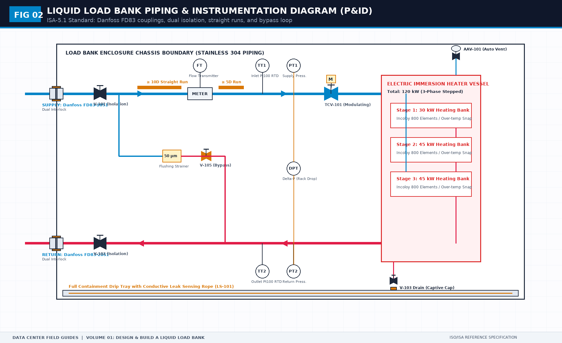
Public briefs for high-density racks quote multiples: performance against an older platform, memory bandwidth, link bandwidth. Those numbers are not coolant flow, not heat rejection, and not a setpoint. They describe a different product claim. Putting one on a load bank sheet feels precise. It is the wrong unit.
The duty comes from the specification then in force for the test you are running. Cite that document by title and the date you read it. If you cannot cite it, the cell stays blank. A blank cell stops a fabricator. A borrowed multiple starts a fabricator on a fiction.
The same rule applies to a slide that says "up to" a flow or a temperature. "Up to" is not a test point. A test point is a value, a unit, a place in the loop, and the sentence it supports. One of those missing, and you do not have a duty. You have a range someone can pass by accident.
When the specification and a public page disagree, the specification wins for the build. The public page can stay in the reading list. It does not get a line on the acceptance sheet.
1. First-Principles Engineering Formulation and Governing Mathematics
In high-density data center environments, verbal summaries and qualitative status tiles routinely obscure incipient physical failures. Whether auditing a 120 kW liquid-cooled rack boundary, evaluating a 1-second telemetry time series, or verifying plant redundancy prior to handover, the governing physical relationship for this protocol is expressed as:
When any term on the left-hand or right-hand side of this relationship is left unmeasured, inferred from an uncalibrated nameplate, or averaged across an unverified time window, the resulting engineering record cannot support a valid operational signature. Field engineers must verify each physical variable independently using NIST/ISO 17025 traceable instruments before proceeding to the next gate in the sequence.
| Audit Verification Parameter | Unacceptable / Defective Field Practice | Auditable First-Principles Requirement | Mandatory Action on Failure |
|---|---|---|---|
| Primary Boundary Definition | Implied by vendor brochure or slide deck | Explicitly bounded on stamped P&ID / SLD with tag IDs | Halt acceptance; issue formal boundary clarification |
| Measurement & Telemetry Proof | Single uncalibrated display reading or 60-sec average | Calibrated Class A/0.5S sensor with 1-sec UTC timestamp | Reject dataset; classify point as 0x40 Stale or 0x80 Bad |
| Pass / Fail Acceptance Gate | Qualitative "Looks OK" or "Within Normal Range" | Quantitative numerical corridor cited from revision in force | Log Category A/B defect; withhold retainage or permit |
| Custody & Sign-Off Record | Single bundled "Accepted" signature at end of meeting | Scoped, dated sentence naming exact proved & unproved lines | Strike unsupported claims; issue Conditional Refusal |
2. Deep-Dive Technical Protocol and Field Implementation
The following field protocol—adapted directly from Volume 01: Design and Build a Liquid Load Bank for NVL72 Racks—establishes the step-by-step verification mechanics required on the data hall floor:
A load bank can meet every function in the previous chapter and still be the wrong machine. Functions say it can be adjusted and read. Duty says what it must be able to become. Those are different. A laboratory heater with a flow meter can be adjusted and read. It still may not stand in for an NVL72-class rack, because the rack’s liquid problem is not “some heat, some water.” The change that matters is the flow regime on the rack side.
High rack-side flow is the point of this class of liquid cooling. The load bank has to be able to live in that regime, not in a gentler loop that happens to use the same word, coolant. A unit sized for a small temperature rise at a modest flow will look excellent on a bench and useless at the manifold, or the reverse: it will demand a temperature rise the rack will never show, and everyone will conclude the rack is “too cold” when the rack is simply moving more liquid.
This book will not publish the vendor’s current flow, pressure, or temperature window. Those figures belong to a document with a revision. Your duty sheet cites that document. When the revision changes, the sheet changes. The metal might not, and that is a project decision, not a fact this book can freeze.
Heat is not a nameplate
Electrical power into the elements and heat into the liquid are not the same quantity. They are close when the unit is well built, steady, and not dumping heat into the room or into a mass that has not warmed up. They are not close during the first minutes of a step, or when a cabinet is open, or when a portion of the power is lost in drives and supplies that do not touch the liquid. If your acceptance treats nameplate kilowatts as heat into the loop, you will accept a unit that cannot do the thermal job, or you will reject a unit that can, because the first minutes looked short.
Write both numbers on the sheet, with different names. Commanded electrical power. Inferred heat into the liquid. The inference needs flow and both temperatures, which is why those readings are not optional ornaments. The inference also needs you to say whether you are in steady state. A step that has not been held is not a heat measurement. It is a transient. Transients matter, but they are a different row.
You do not need a published formula with borrowed constants to use this. You need the habit of asking, at every plateau: does the temperature rise, times the flow, tell a story that matches the electrical power within a band that does not embarrass the conclusion. If you cannot form that story, you are not yet allowed to say the load bank loaded the loop. You are allowed to say the contactors closed.
The educational baseline sandbox: 120 kW virtual rack derivation
To ensure this book provides concrete numerical yardsticks without violating vendor non-disclosure or freezing a proprietary datasheet, we establish a non-proprietary educational reference model. (See Figure 07 for the complete first-principles derivation sheet).
Assume a baseline virtual AI rack operating in a secondary liquid loop under standard testing conditions:
- Nominal Thermal Duty: P_thermal = 120.0 kW
- Secondary Coolant: 25% Propylene Glycol / 75% Water by volume (PG25)
- Coolant Physical Properties (@ 40°C mean bulk): Density ρ = 1025 kg/m³, Specific Heat C_p = 3.980 kJ/(kg·K)
- Design Thermal Delta-T: Supply T_supply = 35.0°C, Return T_return = 45.0°C (ΔT = 10.0 K)
From first-principles thermodynamics (P = ṁ · C_p · ΔT), the required mass flow rate is:
Converting mass flow to volumetric flow rate (Qv = ṁ / ρ):
Now perform the hydraulic pipe velocity verification. Across a standard DN32 sanitary stainless pipe (inner diameter d_i = 32.0 mm, cross-sectional area A = 8.04 × 10^{-4} m²):
This velocity sits safely below the standard 3.0 m/s fluid erosion threshold for stainless steel piping and EPDM hoses, preventing acoustic resonance, cavitation, and particulate wear.
Finally, establish the hydraulic resistance target. The stand-in must match the rack's pressure drop curve (ΔP = k · Q_v²). At the rated 176.5 L/min flow, nominal differential pressure is targeted at ΔP_nominal = 115 kPa (1.15 bar), with an allowable prototype acceptance band of ± 10% (103.5 kPa to 126.5 kPa).
With these exact sandbox equations, your project sheet has a mathematically closed baseline. If your actual cited interface specification later demands 140 kW at 190 LPM, you adjust the variables in daylight. The method of calculation remains identical.
The set, not the list
Four liquid quantities and one electrical quantity travel together. Heat into the liquid. Flow. Differential pressure. Supply temperature. Return temperature. Electrical power sits beside them as the means, not as a substitute.
If any one is missing, the others can tell a false story that looks like engineering.
Heat without flow: you may be heating a trapped volume, a dead leg, or a unit that has begun to boil in a place you did not intend. The temperature will move. The movement will be frightening and uninformative.
Flow without temperatures: a high flow can mean the stand-in is realistic or that the heat is off. You cannot tell. Low flow can mean a realistic reduced step or a blockage. You cannot tell.
Temperatures without flow: a small rise can mean high flow, which may be what you wanted, or failed heaters, which is the opposite. A large rise can mean the rack-like condition or a hose on its way to a kink. The rise alone does not know.
Pressures without flow: you can see that the loop is stressed and not know whether you are at the duty flow or at a trickle through a half-closed valve. Stress at the wrong flow is not the rack’s resistance. It is an accident with a gauge.
Flow and temperatures without differential pressure: you can balance the heat and still present the CDU with a hydraulic surprise. The CDU will then move off the operating point you thought you were testing, and the later data book will try to explain a control reaction that began in your omission.
Electrical power without the liquid set: you can prove the feeders warmed and not prove the coolant did.
So the duty sheet is one operating point, written as a set, plus the range around it that acceptance must visit. A list of five unrelated wishes is how you get a unit that can reach each number on a different afternoon.
What an operating point contains
For each quantity in the set, answer three questions only.
Why is it measured. If the answer is “the display had a spare channel,” delete it or demote it to optional. A quantity earns its place by changing a decision: hold the step, stop the step, or refuse to call the point valid.
Which side of the boundary is it measured on. Rack side, load-bank side, and CDU side are not interchangeable. A supply temperature at the CDU outlet has already been through a pump and a hose. A supply temperature at the load-bank inlet is the liquid the heaters see. Pick the side that matches the sentence you are trying to make true. Then, if the later test needs the other side, add it as a second point rather than reusing the name.
What false story a bad reading tells. Write the sentence. “A low temperature rise will be reported as high performance when the heaters are actually off.” That sentence is the reason the flow meter and the power reading have to sit next to the temperatures. If you cannot write a false story, you do not understand the point yet. Leave it marked unknown. Do not fill it with a plausible unit and a made-up accuracy.
Nominal, steps, and overload
The duty point is the nominal stand-in: the set you mean when you say the unit can represent the rack at the condition you care about. Around it, acceptance visits a reduced step, a middle step, full, and zero. After those are clean, it visits a short overload whose level and dwell are defined on the acceptance sheet, not invented in the room.
Do not copy those levels from a prototype report you once saw. A percentage that was right for one element arrangement is a superstition for another. The rule is procedural. The sheet must name the levels and the dwells before the day. The levels must be fractions of a duty point you can cite, or values you explicitly accept responsibility for because no citation exists yet. Responsibility is allowed. Pretending the number came from a standard is not.
Dwell is part of the point. A flow you touched and left is not a flow you held. State the dwell in time, or state the criterion that ends the dwell: temperatures no longer changing in a way that would alter the heat story. The second form is harder to cheat and harder to write. Use it if you can say what “alter the heat story” means in the export. If you cannot, use a clock and be honest that the clock is a convenience.
Overload is not a second nameplate. It is a short visit above the rated set to see whether the unit stays stable and whether heat still leaves by the path you designed. It is not a license to publish a higher continuous rating. The limitations page should say the overload is a transient acceptance point, not a new nominal, unless you truly designed for continuous duty there. Most prototypes did not. Say so.
High flow as a design driver
Why does flow regime change the machine, rather than merely changing a setpoint.
At higher flow, the same heat produces a smaller temperature rise. Sensors and records that were adequate for a large rise become arguments about noise. You may need the check method, the interval, and the dwell to be tighter, not because this book declares a new accuracy class, but because the story you are trying to tell got smaller. Write that risk on the sheet: “temperature rise at the duty flow may be small; do not accept the point on temperature alone.”
At higher flow, fittings, bends, and a half-closed valve dominate differential pressure. A unit that was “low pressure drop” at a gentle flow can become the dominant resistance at the rack flow, or it can cavitate, pull air, or collapse a hose that looked fine when empty. The liquid-path chapter is where you design for that. The duty chapter is where you admit it. Put “intended flow band” on the sheet even when the numbers are still a citation. A blank band is a reminder. A missing row is how the shop sizes for the heater and forgets the water.
At higher flow, maldistribution inside the unit matters more. Parallel paths that shared nicely at low flow will not share nicely when one path has a little extra hose. The heat-path chapter deals with modules and branches. Here, the duty consequence is: if you claim a single flow reading represents the unit, you must say that the internal paths are not separately loaded, or you must measure the branches you will separately load. A single meter on a header is a header meter. It is not a module meter.
None of this requires you to insert a liters-per-minute figure from a paper or a slide. It requires the duty sheet to treat flow as a driver of sensor choice, valve authority, and what “one reading” means. If your sheet has kilowatts in bold and flow in a footnote, you have built the gentle heater again, in prose.
The window and the point
A specification window is a region: flows, temperatures, and pressures the rack side is allowed to see. An operating point is a place inside or on that region where you will sit. Acceptance visits several places. It does not “cover the window” by waving at it.
Pick the places for reasons. Nominal, because that is the claim. A reduced flow, because valve authority and meter behavior change there, and because some tests will ask for it. A high flow within the cited window, if nominal is not already there, because that is the regime you are afraid of. A supply temperature at the cool end and, if the window is wide, at a warm end, because density, viscosity, and heater surface temperature are not identical across the window. If you do not know whether the window is wide, the citation is unfinished. Do not invent a second temperature to look thorough.
Write a column called “why this place.” If the only answer is “to have more rows,” delete the row. Extra rows cost dwell time and create false failures.
What changes when the revision changes
Interface specifications move. A field guide that embedded last year’s window would become a quiet lie. Your process has to be dull enough to survive that.
When a cited revision changes, someone rereads the duty set and marks each cell: still inside what we built, no longer inside, or unknown. Cells that are no longer inside do not auto-update. The unit does not grow a larger pipe because a PDF changed. You either accept a limitation (“this unit represents the previous window, not the current one”), or you modify the unit and re-accept the affected gates, or you stop claiming the stand-in. All three are honorable. Pretending the old acceptance still covers the new window is not.
Record the revision on the duty sheet itself, not in an email. The acceptance record cites the sheet revision. Two hops is enough to reconstruct history. Three hops, through a chat log, is how you lose.
The loop you connect to on the day
Duty is about the unit. The unit cannot show duty if the loop on the day cannot absorb it. A bench loop with a small reservoir and a tired pump will overheat or run out of flow and you will condemn the prototype. Write, on the acceptance sheet, the minimum the temporary loop must provide: it must absorb the heat of the longest dwell, and it must be able to deliver the flow you intend to demand, at a pressure the unit is allowed to see. Those are setup requirements. They are not a second load bank. They stop you from running Gate 3 against a loop that made the test impossible.
If you do not know the temporary loop yet, mark it unknown with a date. Do not leave it implicit. Implicit loops are always assumed to be adequate, and they rarely are.
Composite: the impressive nameplate
A shop builds a unit whose electrical nameplate is large. On the bench they run it at a modest flow because the bench pump is modest. Temperature rise is easy to see. Everyone relaxes. Months later the unit is asked to follow a rack-side flow that is several times the bench flow. Temperature rise shrinks into the noise of the sensors. Differential pressure across a restrictive internal path climbs. The same people say the rack specification is unrealistic. The unit was accepted against the wrong set. The nameplate did exactly what a nameplate does: it described the heaters, not the stand-in.
The fix is not a better adjective on the nameplate. The fix is a duty point written as a set, cited, and visited at that set before anyone calls the prototype done.
Composite: the borrowed window
Another team pastes a table of flows and temperatures from a slide into the duty sheet and removes the slide’s title. The numbers are now “the standard.” A later revision of the real interface document moves a limit. The sheet still has the old numbers, and no one can say where they came from. Acceptance passes against the souvenir. The first real hookup fails a limit the souvenir no longer matches.
The fix is the citation column. Numbers without a title and revision are not a duty. They are a rumor. If you are not allowed to copy the numbers into a book, you are also not allowed to copy them into a sheet without the citation. The permission to use them on the project is not the same as the permission to detach them from their source.
Electrical duty, briefly
The electrical feed must be able to support the highest step you will command, including the overload dwell if the overload is electrical and not only thermal. Record voltage and frequency as citations to what the hall, or the bench, will actually provide. Record whether the unit’s protection assumes a neutral, a ground, or a particular breaker behavior only so far as a wrong assumption would make the safe-state chapter false. Do not turn this into a power-system study. Do notice the common cheat: thermal acceptance run from a temporary feed the hall does not have. If the delivered unit needs a different feed, the power interface line is not accepted.
Steady state, step, and trip
Give the duty sheet three kinds of rows, so people stop arguing about which kind a number is.
Steady rows are the set at a plateau, after the dwell criterion. Step rows are the command to move, and what must be true during the move: no trip, no stale data, flow not collapsing unless the step was a flow step. Trip rows are not duty in the sense of output. They are the conditions under which duty must end. Put a pointer to the safety chapter rather than inventing trip values here. If a trip value is in the cited specification, cite it. If it is your choice, label it as your choice.
This separation keeps overload from being used as a steady rating, and keeps a trip setpoint from being used as a performance target. Targets and limits are different directions. A unit that runs best at its trip point is a unit you do not understand.
What NVIDIA publishes on the data-center site
Read on 11 October 2026 from https://www.nvidia.com/en-us/data-center/ and the product pages linked from it. These are NVIDIA’s pages. The sentences below are a short extract of configuration facts that bear on a load bank. They are not a copy of the pages, and they are not an interface specification.
The site is a catalog. It describes accelerated computing, AI factories, networking, and rack products. It does not, on the pages read for this draft, publish the coolant flow, supply temperature, differential pressure, or fitting family a load bank must meet. Those cells stay blank until the datasheet or the rack specification then in force fills them. Do not invent them from the catalog.
Two rack pages are the ones this book can use.
GB200 NVL72, product page https://www.nvidia.com/en-us/data-center/gb200-nvl72/. NVIDIA describes it as rack-scale and liquid-cooled. The published configuration is 36 Grace CPUs and 72 Blackwell GPUs, one NVLink domain. The same page’s specification table, which you should re-read rather than trust this sentence if the page has moved, lists 13.4 TB of HBM3E, 17 TB of LPDDR5X, 130 TB/s of NVLink bandwidth, and 2,592 Arm Neoverse V2 cores. A datasheet is linked from that page. Performance multiples against H100 are on the page. They are not duty. They do not enter a plateau.
GB300 NVL72, product page https://www.nvidia.com/en-us/data-center/gb300-nvl72/. NVIDIA describes it as fully liquid-cooled and rack-scale: 72 Blackwell Ultra GPUs and 36 Grace CPUs. The specification block on that page lists 130 TB/s NVLink bandwidth, 37 TB fast memory, 20 TB GPU memory, 17 TB LPDDR5X, and the same 2,592 Arm cores. A Blackwell Ultra datasheet is linked from the page. The 50x and 30x figures on that page are projected performance claims. They are not heat, flow, or pressure.
Vera Rubin NVL72 is listed on the same catalog as a later rack-scale product. Cite it only if that is the generation you are standing in for. Do not assume its liquid interface matches GB200 because the name still says NVL72.
What this does to the duty sheet is narrow. The stand-in is liquid, not air. The unit represents one rack of the generation you cite, not the building, not the network, and not the GPU’s FLOPS. Memory bandwidth and NVLink bandwidth are not coolant flow. A load bank that can match a published FLOPS number and cannot tell you flow and both temperatures has not met this chapter. Write the generation name and the page date on the duty header. Leave flow, temperatures, and differential pressure for the datasheet revision you are allowed to use.
Other links on the catalog, and why they stay out of the heat story: the data-center GPU line card, the qualified system catalog, and NVIDIA-Certified Systems, for identifying a server, not for sizing a hose. MLPerf, for workload benchmarks, not for a thermal plateau. Mission Control, for factory operations software, not for the local stop. Spectrum-X, Quantum InfiniBand, and BlueField, for the network, which this book does not accept. MGX, as a modular server reference, only if the interface owner says the rack you will mate to is an MGX liquid-cooled variant. DSX, as a cost-per-megawatt story, is not a kilowatt into your liquid.
Public sources for this chapter
The duty set stays blank until a cited revision fills it. NVIDIA’s public page establishes the class: liquid-cooled, rack-scale, not a gentle air load. The datasheet linked from that page is the place interface numbers would live, if you are allowed to use them on the project. Do not copy marketing multiples from the page into a cell. A factor against an older platform is not a flow and not a temperature. ASHRAE thermal guidance, in whatever edition you are licensed to read, is where classes and recommended environments are defined. Those classes are not reprinted here. If your duty cites an ASHRAE class, the citation includes the edition, and the numeric window stays on the project sheet. ANSI/ASHRAE 90.4 is an energy standard for data centers. It does not set the load bank’s plateau. Do not let a hall energy claim migrate into this duty set.
3. Field Verification Checklist and Instrumentation Hygiene
To execute this protocol without introducing measurement bias or scope ambiguity, the responsible engineer enforces four mandatory field rules:
- Instrument Traceability Before Observation: Verify that every thermometer (4-wire Pt100 RTD Class A), pressure transducer (≤ ± 0.1% span), flowmeter, balometer, or power analyzer carries a current calibration certificate and passes a pre-test zero/span check on the day of the walk.
- Synchronized Time-Series Capture: Align all digital loggers and gateway pollers to a single UTC reference clock (via IEEE 1588v2 PTP at ± 1 ms for electrical Sequence of Events, or NTP at ± 10 ms for thermal/hydraulic dwells). Never merge unsynchronized CSV files by row index.
- Explicit Isolation of Disturbances vs. Control Handles: Hold upstream supply temperatures, parallel cabinet loads, and containment door states constant during the observation dwell so that transient plant drift is never mistaken for steady-state equipment performance.
- Written Record Prior to Signature: Record every boundary tag, measured value, uncertainty tolerance, and open limitation in ink on the controlled project sheet before leaving the equipment line-up.
Frequently Asked Questions (FAQ)
Why does "A marketing multiple is not coolant flow" matter during high-density data center commissioning and operations?
Why marketing claims like '30x better than air' cannot size a liquid load bank or pipe manifold without explicit mass flow, PG25 specific heat, and Delta-T. When project teams bypass this rule to meet a commercial schedule milestone, unverified physical assumptions—such as hidden hydraulic pressure drops, unlogged polling gaps, unblanked bypass leakage, or uncalibrated sensor offsets—transfer directly into live 24/7 production as latent single points of failure.
How do you quantitatively verify compliance with "liquid cooling coolant flow calculation" on the physical floor?
Compliance is verified by executing the governing mathematical balance (ṁ = Pthermal / (Cp · Δ T) = 120.0 kW / (3.980 kJ/(kg·K) × 10.0 K) = 3.015 kg/s ⇒ 176.5 L/min) using independent, calibrated field instruments across a stabilized steady-state dwell window (minimum 15 to 30 minutes for thermal and hydraulic systems), and confirming that the discrepancy between primary and secondary measurements remains strictly within the pre-declared acceptance band.
What should an engineer do if a contractor or vendor submits a report that violates this protocol?
The reviewing engineer must refuse to sign the broad acceptance sentence, mark the specific line item as Unproved / Defective on the official audit sheet, and either require a witnessed re-test under a corrected script or isolate the unproved scope under a time-bounded Conditional Acceptance with a 150% to 200% financial retainage escrow holdback.
From Design and Build a Liquid Load Bank for NVL72 Racks, Tristan, Data Center Field Guides.
Related: Two documents before you cut metal.
Master the Complete Protocol: Design and Build a Liquid Load Bank for NVL72 Racks
A Field Guide to Interface Boundaries, P&ID Hydraulics, Thermal Envelopes, and Acceptance Sheets
Stop relying on contractor spreadsheets and vendor marketing claims. This field guide provides the complete, auditable verification binder—including physical equations, inspection stations, acceptance thresholds, and signed refusal templates.