A Nameplate Is Not Used Capacity: Data Center 2N Power Derating, Live Metering, and Redundancy Math
Direct Answer Block: In critical facility operations, equipment nameplate ratings, architectural design kilowatts, and one-line redundancy labels (N+1 or 2N) must never be entered into the daily "Used Capacity" or "Available Capacity" cells signed by the shift manager. A valid capacity entry requires a live, time-stamped measurement from a calibrated revenue or EPMS meter, combined with verified single-fault derating math. If the metered point is missing or stale, the capacity cell must remain explicitly blank with a documented reason.
Every day, facility managers are asked to sign off on a daily capacity summary reporting three numbers for power and cooling: Installed Capacity, Used Capacity, and Available Redundant Capacity. Across the industry, teams routinely corrupt this record by filling the cells with nameplate ratings stamped on transformer enclosures, design load estimates from six-year-old drawings, or unverified marketing claims from a slide deck.
A steel nameplate riveted to a chiller or a UPS cabinet tells you the maximum continuous thermal or apparent power the manufacturer tested at standard factory reference conditions (25^\circC ambient, 1.0PF, sea level, clean condenser tubes). It does not tell you what the machine can deliver tonight at 42^\circC outdoor dry bulb with fouled heat exchangers, and it certainly does not tell you how many kilowatts the data hall is drawing right now.
1. The Four Distinct Kilowatt Numbers in a Data Hall
To prevent capacity accounting fraud—whether accidental or commercial—facility engineers strictly separate four numbers that share the unit of kilowatts (kW) or kilovolt-amperes (kVA) but belong to completely different physical domains:
| Metric Classification | Physical Definition | Valid Data Source | Allowed in Shift "Used Capacity" Cell? |
|---|---|---|---|
| 1. Nameplate Rating (Pnameplate) | OEM factory test limit under nominal reference conditions (e.g., 2,500kVA at 0.9PF). | Equipment stamped data plate / factory FAT certificate. | NO. Static factory upper bound; ignores site derating and actual load. |
| 2. Design / Contracted Load (Pdesign) | Theoretical maximum load allocated on engineering drawings or tenant leases. | MEP Basis of Design (BoD) or commercial lease schedule. | NO. Commercial reservation or drawing estimate, not physical flow. |
| 3. Live Measured Load (Pmeasured) | Real-time active/apparent power measured by calibrated CTs/PTs or ultrasonic flow/Δ T meters. | Live EPMS/BMS point with timestamp tmeas and 0x00 Good quality flag. | YES. The only number permitted in the Used Capacity cell. |
| 4. Tested Redundant Capacity (Ptested) | Maximum load demonstrated during a witnessed pull-the-plug IST fault test with 1 path isolated. | Signed Level 5 IST Commissioning or Annual Black-Building Test record. | Reference Only. Defines the true upper ceiling for Available Capacity. |
2. Why "Blank with a Reason" Beats a Fabricated Number
When an Electrical Power Monitoring System (EPMS) Modbus gateway freezes or a branch circuit meter loses its RS-485 serial link, operations teams face a temptation: copy yesterday's load reading, or substitute the tenant's design kilowatt allocation so the daily spreadsheet has no empty cells.
Never fill a missing measurement cell with a design number. Once a design kilowatt or a corridor whiteboard estimate is typed into the official Used Capacity column, upstream capacity planners, commercial sales teams, and automated scripts ingest that number as an empirical measurement. Six months later, that fabricated figure will be cited as historical proof that the busbar carried 1,800kW safely.
The engineering rule for the shift logbook is absolute:
- Every capacity cell requires three elements: a named meter source, a measurement timestamp, and an engineering unit ( carefully distinguishing active power in kW from apparent power in kVA).
- If the meter is offline, uncalibrated, or reporting a stale timestamp, leave the numerical cell blank and write the explicit telemetry defect code beside it:
BLANK — Meter EPMS-UPS2A-OUT Stale since 01:14 UTC (Ticket #4409). - Never add a live measured load from Bus A (920kW measured) to a design estimate for Bus B (1,000kW design) to report a "Total Hall Load of 1,920kW." Adding a measurement to an assumption produces an uncalibrated fiction that belongs in neither column.
3. The N+1 and 2N Redundancy Illusion
Redundancy notation on a single-line diagram is an architectural intention, not an operational guarantee. Seeing Chiller Plant: N+1 (4 x 1,500 Ton) printed on a wall diagram does not tell the night-shift manager how much cooling capacity remains if Chiller 1 trips tonight.
DESIGN N+1 CLAIM vs. ACTUAL PHYSICAL DERATING
| DRAWING CLAIM (4 x 1,500 kW = 4.5MW N+1 Redundant Capacity) | NIGHT SHIFT REALITY (43°C AMBIENT, CHILLER #2 DERATED ON HIGH HEAD) |
|---|---|
| Chiller 1: 1,500 kW (Nameplate) Chiller 2: 1,500 kW (Nameplate) Chiller 3: 1,500 kW (Nameplate) Chiller 4: 1,500 kW (Standby) | Chiller 1: 1,280 kW (Ambient Cap) Chiller 2: 950 kW (Fouled Cond.) Chiller 3: 1,280 kW (Ambient Cap) Chiller 4: 0 kW (LOTO Open!) |
| Claimed N Capacity: 4,500 kW Current IT Load: 3,400 kW (PASS) | True N-1 Capacity: 2,230 kW Current IT Load: 3,400 kW (FAIL!) |
To convert a design redundancy graphic into an operational capacity number, the shift manager must apply three physical derating checks:
- Active Isolation & LOTO Subtraction: Any machine currently under Lockout/Tagout, in local
HANDbypass, or suffering an unreset trip is subtracted from Ntotal immediately. An N+1 lineup with one unit on LOTO is an N+0 non-redundant plant. - Environmental & Power Factor Derating: Air-cooled chillers and dry coolers lose 1.5% to 2.5% of net heat rejection capacity for every 1^\circC ambient temperature rise above design reference. Similarly, transformer and UPS kVA capacity must be derated for non-unity load power factor (PF = P / S) and harmonic current crest factor.
- Witnessed Transfer Proof: Unless an actual pull-the-plug test demonstrated that N-1 units can pick up and hold the current load without crossing low-suction pressure or high-head trip limits during the 60-second staging transient, the N+1 label remains a design hypothesis. Note the drawing claim in the margin; do not certify it as tested available capacity.
4. Handling Future IT Load Forecasts
Commercial capacity teams routinely track "Committed Future IT Load" (racks sold under contract but not yet deployed or energized). Future IT load is a commercial plan, not a physical state. It must never be mixed into the shift manager's Used Capacity cell, nor subtracted silently from Available Operational Capacity unless the exact reservation formula is written in a single auditable sentence on a separate planning ledger. The shift logbook records the physics of the plant tonight, not the sales pipeline for next quarter.
Frequently Asked Questions (FAQ)
Why can't we use the breaker trip rating or UPS nameplate kVA to calculate available capacity?
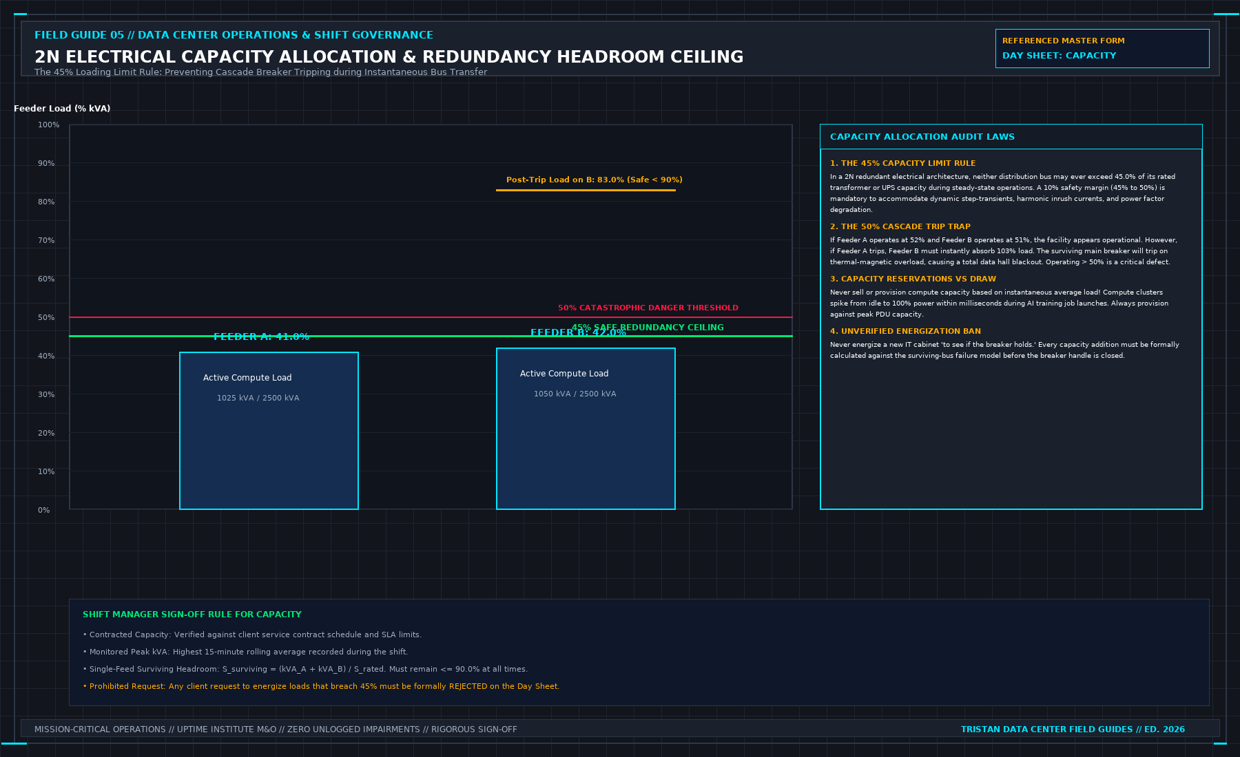
A breaker's nominal rating (e.g., 4,000A) and a UPS nameplate rating (e.g., 2,000kVA) do not account for continuous-duty NEC/IEC derating factors (80% for standard molded-case breakers), ambient switchgear room temperatures above 40^\circC, load power factor (kW = kVA × PF), battery recharge current overhead (10%–15%), or the 45% 2N transfer ceiling required to survive a companion bus failure.
What should a shift manager write if the main PDU power meter communication fails during the shift?
The shift manager must leave the "Used Capacity" numerical field blank (or enter N/A - COMMS FAULT) and log the exact timestamp when the meter point transitioned to STALE or BAD quality, along with the corrective maintenance ticket number. If a local physical panel ammeter was walked and read during the shift round, that reading may be recorded separately with the explicit annotation LOCAL PANEL READ @ [TIME].
How do you distinguish between Design Redundancy and Operational Redundancy on the shift log?
Design Redundancy is the static topology shown on the architectural one-line diagram (e.g., 2N or N+1). Operational Redundancy is the live fault-tolerance state tonight after subtracting any equipment under LOTO maintenance, applying ambient/harmonic deratings, and verifying that live load is below the single-fault transfer threshold.
From Run the Data Center Day, Tristan, Data Center Field Guides.
Related: A green tile is not acceptance.
Master the Complete Protocol: Run the Data Center Day: What the Manager Must Sign Before the Shift Ends
2N Redundancy Mathematics, 6 Inspection Stations, Shift Handovers, and SOP/MOP/EOP Protocols
Stop relying on contractor spreadsheets and vendor marketing claims. This field guide provides the complete, auditable verification binder—including physical equations, inspection stations, acceptance thresholds, and signed refusal templates.