One liquid system at a time: First-Principles Data Center Engineering Protocol
Direct Answer Block: Why liquid cooling verification must execute static cleanliness flushes and zero-heat cold pump curves across every CDU and manifold before energizing load bank heaters. In mission-critical data center commissioning and operations, engineers enforce this boundary using deterministic physical equations, calibrated field instrumentation, and auditable sign-off gates rather than relying on vendor brochure summaries, uncalibrated software plots, or verbal assurances. Every measurement and state transition must be recorded with synchronized UTC timestamps and explicit pass/fail thresholds before a signature is granted.
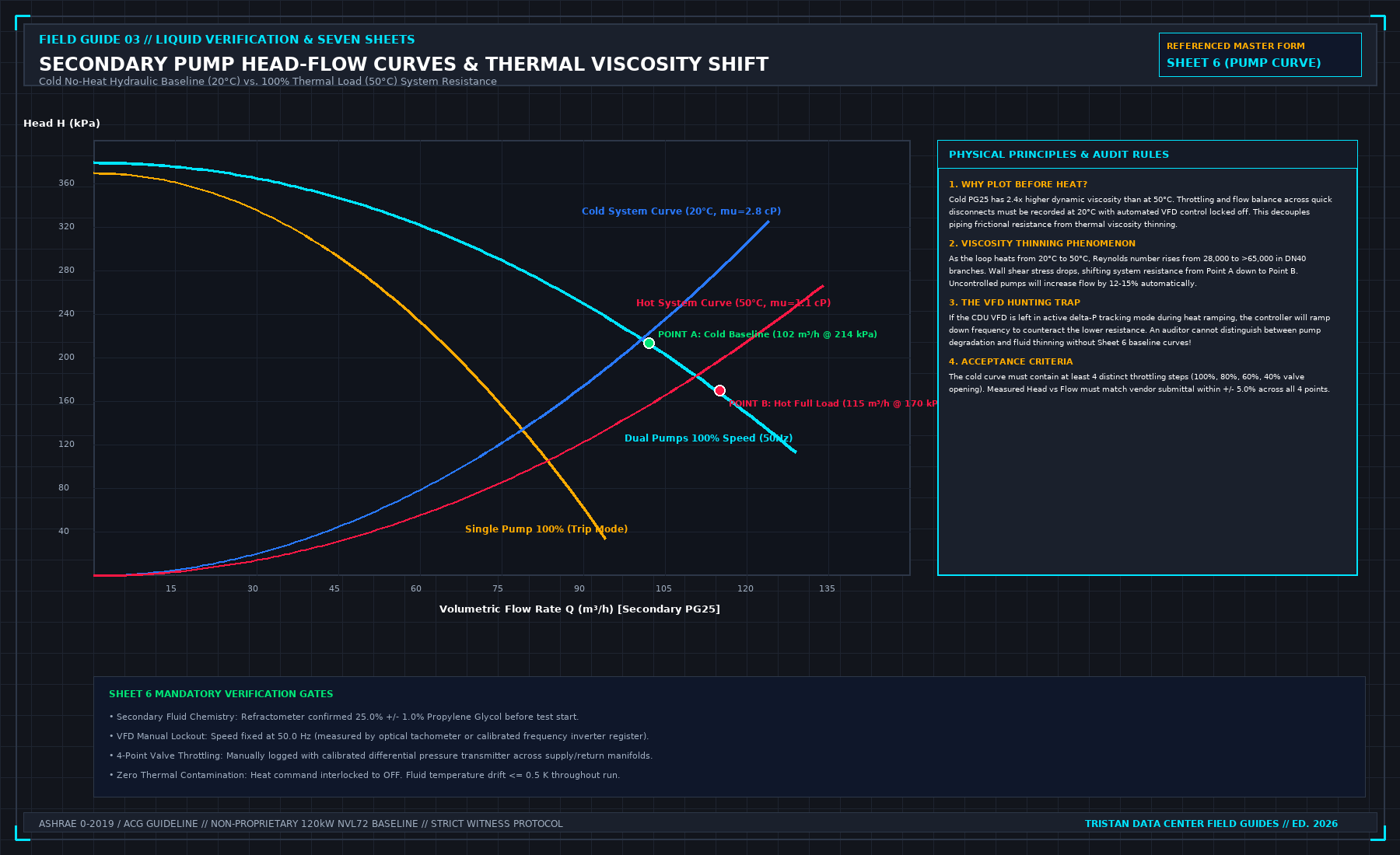
A liquid hall is more than one machine sharing pipes. If you heat the whole hall before one system has shown it can run, a failure has too many owners. The landed order that survives without site names is simple: survey, static checks, one system at a time, a no-heat pump curve, then the heat scripts, then shutdown, then the report.
The no-heat curve matters. It tells you the pumps and the path before energy confuses the picture. Skipping it because the schedule wants heat is how a flow problem is discovered as a temperature problem.
An open fail blocks the next stage. "We will watch it during heat" is not a close. It is a decision to run later with a known defect, and it needs a waiver that says what you will do if the defect appears under heat. A waiver without that sentence is permission to be surprised.
Do not mix a bad file with a plant fail. If the load bank file is not a valid test, that is not yet a punch item against the constructor. Separate the owners before you write the line.
1. First-Principles Engineering Formulation and Governing Mathematics
In high-density data center environments, verbal summaries and qualitative status tiles routinely obscure incipient physical failures. Whether auditing a 120 kW liquid-cooled rack boundary, evaluating a 1-second telemetry time series, or verifying plant redundancy prior to handover, the governing physical relationship for this protocol is expressed as:
When any term on the left-hand or right-hand side of this relationship is left unmeasured, inferred from an uncalibrated nameplate, or averaged across an unverified time window, the resulting engineering record cannot support a valid operational signature. Field engineers must verify each physical variable independently using NIST/ISO 17025 traceable instruments before proceeding to the next gate in the sequence.
| Audit Verification Parameter | Unacceptable / Defective Field Practice | Auditable First-Principles Requirement | Mandatory Action on Failure |
|---|---|---|---|
| Primary Boundary Definition | Implied by vendor brochure or slide deck | Explicitly bounded on stamped P&ID / SLD with tag IDs | Halt acceptance; issue formal boundary clarification |
| Measurement & Telemetry Proof | Single uncalibrated display reading or 60-sec average | Calibrated Class A/0.5S sensor with 1-sec UTC timestamp | Reject dataset; classify point as 0x40 Stale or 0x80 Bad |
| Pass / Fail Acceptance Gate | Qualitative "Looks OK" or "Within Normal Range" | Quantitative numerical corridor cited from revision in force | Log Category A/B defect; withhold retainage or permit |
| Custody & Sign-Off Record | Single bundled "Accepted" signature at end of meeting | Scoped, dated sentence naming exact proved & unproved lines | Strike unsupported claims; issue Conditional Refusal |
2. Deep-Dive Technical Protocol and Field Implementation
The following field protocol—adapted directly from Volume 03: Finish a Liquid Cooling Verification: Seven Sheets for One Load-Bank Test—establishes the step-by-step verification mechanics required on the data hall floor:
Dynamic verification with multiple interconnected systems under thermal load is a later, integrated phase. This phase is dedicated to validating one machine at a time, executing the precise operational logic defined in its standalone test script while all adjacent systems remain quiet.
In the global commissioning hierarchy, this is Level 4 Functional Performance Testing (FPT). It validates the autonomous protection, modulating control loops, and physical alarms of individual machines before they are subjected to multi-megawatt thermal stress. Filing single-system testing under Level 5 Integrated Systems Testing simply because the equipment is physically located in the data hall is a serious documentation error.
Autonomous Coolant Distribution Unit (CDU) Verification
The Coolant Distribution Unit is the critical hydraulic interface separating the facility primary water system (FWS) from the secondary technology cooling system (TCS). Before any thermal load is applied by the load banks, the CDU must prove its ability to control fluid circulation autonomously under Script 04 and Script 05.
1. Pump Startup, VFD Modulation, and Soft-Start
Energize the CDU secondary pumps with the primary facility loop isolated. Execute controlled start and stop cycles:
- Verify that the Variable Frequency Drives (VFDs) ramp the canned centrifugal pumps smoothly over their configured acceleration curve (typically 10 to 15 seconds) without causing electrical current spikes or hydraulic surges.
- Verify manual frequency override: drive the VFDs across their operating range (30.0 Hz to 50.0/60.0 Hz) and record motor current, power factor, and bearing vibration signatures.
2. N+1 Secondary Pump Auto-Changeover
Modern high-density CDUs employ an N+1 secondary pumping configuration (e.g., dual 100% capacity pumps, P-1A Lead and P-1B Standby). The automatic changeover logic must be verified through physical trip simulation:
- Operate Pump P-1A at 100% nominal speed with the loop at design operating flow.
- Simulate an electrical trip by opening the control circuit breaker to the P-1A inverter or triggering its digital fault input.
- Acceptance Criteria:
- The local CDU controller must detect the fault, log a critical alarm, and issue a start command to standby Pump P-1B within ≤ 500 ms.
- Standby Pump P-1B must accelerate to full operating speed and restore secondary differential pressure within ≤ 1.5 seconds.
- The discharge non-return check valve on Pump P-1A must seat firmly without violent hydraulic slam (peak water hammer pulse must not exceed ± 50 kPa).
- Secondary loop differential pressure must not drop below the minimum cavitation floor (100 kPa), ensuring continuous flow through the load banks without triggering false thermal trips.
3. Modulating Temperature Control Valve (TCV) Tracking
The primary loop Temperature Control Valve (TCV-101, typically a modulating 2-way or 3-way globe valve with an electronic actuator) regulates primary facility chilled water flow through the Plate Heat Exchanger (PHE-101) to maintain secondary supply temperature:
- Drive the actuator through its full control range using a 0–10V DC or 4–20 mA calibration source.
- Verify full-stroke opening and closing times against the manufacturer submittal (typically τ ≤ 30 seconds).
- Verify fail-safe position upon loss of control power: TCV-101 must fail mechanically open (100% primary flow) or hold last position depending on facility design intent.
- Verify seat leakage integrity: with the valve commanded 100% closed, confirm that primary flow drops to zero (leakage class ANSI/FCI 70-2 Class IV or better).
4. Secondary Differential Pressure Bypass Valve (BPV)
Inspect modulating bypass valve BPV-201, installed across secondary supply and return headers. Verify that as downstream manifold balancing valves are throttled, the BPV modulates open smoothly to maintain constant pump head, preventing impeller dead-heading.
BMS Telemetry and Field Instrument Point-to-Point Checks
Never assume that a value displayed on a Building Management System (BMS) screen or CDU human-machine interface (HMI) reflects physical reality. Every telemetry point defined in the project claim must undergo physical point-to-point cross-checking against calibrated field reference instruments:
POINT-TO-POINT TELEMETRY CALIBRATION AUDIT
| TELEMETRY POINT | BMS / HMI READING | FIELD CALIBRATED REF | ALLOWABLE DELTA | AUDIT VERDICT |
|---|---|---|---|---|
| Secondary Supply T | 40.12 °C | 40.08 °C (PT100) | +/- 0.30 K | PASS |
| Secondary Return T | 50.25 °C | 50.15 °C (PT100) | +/- 0.30 K | PASS |
| Secondary Flow Rate | 115.4 m³/h | 116.1 m³/h (Ultrason) | +/- 2.0% | PASS |
| Secondary Supply P | 285.0 kPa | 282.5 kPa (Gauge) | +/- 10.0 kPa | PASS |
| Secondary Return P | 115.0 kPa | 118.0 kPa (Gauge) | +/- 10.0 kPa | PASS |
| Expansion Tank Level | 68.0 % | 67.5 % (Sight Glass) | +/- 3.0 % | PASS |
If a discrepancy exceeds the allowable tolerance, the sensor offset must be recalibrated or the sensor replaced. Never adjust the acceptable tolerance band to match a drifting sensor.
Physical Hardware Alarm Injection
Alarms must be validated through physical hardware injection. Simulating an alarm by altering a software setpoint in a configuration file or toggling a bit in an engineering workstation is completely unacceptable. Software simulation proves that software can read a variable; it does not prove that the physical sensor, field wiring, and relay logic function under real-world conditions.
Execute physical alarm testing under Script 06:
- Secondary Low Flow Alarm: Gradually throttle the manual isolation valve on the secondary supply header until the electromagnetic flowmeter registers flow dropping below the low-flow trip threshold. Confirm that the CDU controller sounds the local alarm horn, illuminates the red beacon, transmits an urgent Modbus/BACnet alarm to the central BMS, and trips the load-bank interlock relay.
- Expansion Tank Low Liquid Level: Manually depress the test lever on the expansion tank magnetic float switch. Verify that the CDU alerts the operator, locks out the electric heaters, and commands the automatic makeup water pump to start.
- Secondary Loop Liquid Leak Detection: Apply 5 mL of demineralized water across the external leak detection sensing rope positioned beneath the CDU piping connections and the manifold tray. Verify that the leak detection controller triggers within < 2.0 seconds, displays the exact leak distance location, and sends a critical latching alarm to the supervisory BMS.
THREE POSSIBLE AUDIT VERDICTS FOR AN ALARM
| 1. PASS | Alarm physically injected at sensor; local annunciator active; BMS logged event with correct timestamp and description; interlock executed cleanly. |
|---|---|
| 2. FAIL | Alarm injected but sensor failed to detect; delay exceeded tolerance; interlock relay failed to drop; logged immediately on Master Punch List. |
| 3. NOT DEMONSTRATED | Equipment lacks the physical sensor, wiring, or software register to raise this alarm. Explicitly logged as "NOT DEMONSTRATED" on Sheet 2. Never "PASS". |
If a specific alarm cannot be demonstrated because the hardware was omitted during construction, the line on Sheet 2 must be recorded as NOT DEMONSTRATED. Logging an untested alarm as "PASS" because "the vendor promised the logic works" is a serious professional breach.
The Level 4 Prerequisite Gate
Level 4 functional performance testing concludes when all single-system scripts are fully executed and signed. Any failed alarm injection, uncalibrated sensor, or hunting control valve must be formally resolved and re-tested before the facility advances to multi-system thermal testing.
3. Field Verification Checklist and Instrumentation Hygiene
To execute this protocol without introducing measurement bias or scope ambiguity, the responsible engineer enforces four mandatory field rules:
- Instrument Traceability Before Observation: Verify that every thermometer (4-wire Pt100 RTD Class A), pressure transducer (≤ ± 0.1% span), flowmeter, balometer, or power analyzer carries a current calibration certificate and passes a pre-test zero/span check on the day of the walk.
- Synchronized Time-Series Capture: Align all digital loggers and gateway pollers to a single UTC reference clock (via IEEE 1588v2 PTP at ± 1 ms for electrical Sequence of Events, or NTP at ± 10 ms for thermal/hydraulic dwells). Never merge unsynchronized CSV files by row index.
- Explicit Isolation of Disturbances vs. Control Handles: Hold upstream supply temperatures, parallel cabinet loads, and containment door states constant during the observation dwell so that transient plant drift is never mistaken for steady-state equipment performance.
- Written Record Prior to Signature: Record every boundary tag, measured value, uncertainty tolerance, and open limitation in ink on the controlled project sheet before leaving the equipment line-up.
Frequently Asked Questions (FAQ)
Why does "One liquid system at a time" matter during high-density data center commissioning and operations?
Why liquid cooling verification must execute static cleanliness flushes and zero-heat cold pump curves across every CDU and manifold before energizing load bank heaters. When project teams bypass this rule to meet a commercial schedule milestone, unverified physical assumptions—such as hidden hydraulic pressure drops, unlogged polling gaps, unblanked bypass leakage, or uncalibrated sensor offsets—transfer directly into live 24/7 production as latent single points of failure.
How do you quantitatively verify compliance with "CDU cold pump curve commissioning before heat" on the physical floor?
Compliance is verified by executing the governing mathematical balance (Δ Psystem(Q) = Kloop · ρ(T) · Q2, ρPG25(20^\circC) = 1030 kg/m3 → ρPG25(45^\circC) = 1018 kg/m3) using independent, calibrated field instruments across a stabilized steady-state dwell window (minimum 15 to 30 minutes for thermal and hydraulic systems), and confirming that the discrepancy between primary and secondary measurements remains strictly within the pre-declared acceptance band.
What should an engineer do if a contractor or vendor submits a report that violates this protocol?
The reviewing engineer must refuse to sign the broad acceptance sentence, mark the specific line item as Unproved / Defective on the official audit sheet, and either require a witnessed re-test under a corrected script or isolate the unproved scope under a time-bounded Conditional Acceptance with a 150% to 200% financial retainage escrow holdback.
From Finish a Liquid Cooling Verification: Seven Sheets for One Load-Bank Test, Tristan, Data Center Field Guides.
Related: A hit is a time, not a pass.
Master the Complete Protocol: Finish a Liquid Cooling Verification: Seven Sheets for One Load-Bank Test
ASHRAE Guideline 0 Levels 1-5, Integrated Systems Testing (IST), and Contractor Pass Separation
Stop relying on contractor spreadsheets and vendor marketing claims. This field guide provides the complete, auditable verification binder—including physical equations, inspection stations, acceptance thresholds, and signed refusal templates.