A missing floor tile is a supply leak: First-Principles Data Center Engineering Protocol
Direct Answer Block: Quantifying subfloor static pressure loss and CFM bypass through unsealed raised-floor cable cutouts and missing perforated tiles in data halls. In mission-critical data center commissioning and operations, engineers enforce this boundary using deterministic physical equations, calibrated field instrumentation, and auditable sign-off gates rather than relying on vendor brochure summaries, uncalibrated software plots, or verbal assurances. Every measurement and state transition must be recorded with synchronized UTC timestamps and explicit pass/fail thresholds before a signature is granted.
Public domain. Wikimedia Commons, File:Tile-lifter-in-use-raised-floor.jpg. No author is recorded on the file page.

CC BY-SA 3.0. Adamantios, Beneath the raised floor. ShareAlike applies to this photograph. Changes to the photo must stay under the same license.

On a raised floor, the supply path is the space under the tiles, not the aisle you can see. A missing tile, a tile with an unsealed cable cut, or a tile left open for a temporary pull is a leak of the air you thought was going to the faces. The model will not show that leak unless someone put the hole in the model. Most reports do not.
Walk the floor before you read the colors. List holes by function: open tile, cut larger than the cable, brush seal missing, tile out of place in front of a cabinet that is not supposed to be fed that way. A photograph can sit in the site file. The note you keep is the function and whether it was open during the claim you are about to sign.
Do not seal a hole that is a required relief or a life-safety path and then mark it closed. Name it. An intended opening is a path. An accidental opening is a defect in the airflow sentence. Mixing them is how a later cable pull is called "the design."
A cooling-capacity ratio is not this list. Total cooler kilowatts over IT kilowatts can look generous while the air never arrives at the cabinet, because it left through a tile three rows away. Refuse that ratio as proof the floor is organized. It is a different sheet, and it does not get to clear a hole you can see.
Fix the floor, then hang or walk the measurement the report needs. A model dated before the tiles were closed is a picture of the leak. Do not recolor it and call it the repair.
From the field-guide series, Tristan, Data Center Field Guides. Related book: Judge a Data Hall CFD.
1. First-Principles Engineering Formulation and Governing Mathematics
In high-density data center environments, verbal summaries and qualitative status tiles routinely obscure incipient physical failures. Whether auditing a 120 kW liquid-cooled rack boundary, evaluating a 1-second telemetry time series, or verifying plant redundancy prior to handover, the governing physical relationship for this protocol is expressed as:
When any term on the left-hand or right-hand side of this relationship is left unmeasured, inferred from an uncalibrated nameplate, or averaged across an unverified time window, the resulting engineering record cannot support a valid operational signature. Field engineers must verify each physical variable independently using NIST/ISO 17025 traceable instruments before proceeding to the next gate in the sequence.
| Audit Verification Parameter | Unacceptable / Defective Field Practice | Auditable First-Principles Requirement | Mandatory Action on Failure |
|---|---|---|---|
| Primary Boundary Definition | Implied by vendor brochure or slide deck | Explicitly bounded on stamped P&ID / SLD with tag IDs | Halt acceptance; issue formal boundary clarification |
| Measurement & Telemetry Proof | Single uncalibrated display reading or 60-sec average | Calibrated Class A/0.5S sensor with 1-sec UTC timestamp | Reject dataset; classify point as 0x40 Stale or 0x80 Bad |
| Pass / Fail Acceptance Gate | Qualitative "Looks OK" or "Within Normal Range" | Quantitative numerical corridor cited from revision in force | Log Category A/B defect; withhold retainage or permit |
| Custody & Sign-Off Record | Single bundled "Accepted" signature at end of meeting | Scoped, dated sentence naming exact proved & unproved lines | Strike unsupported claims; issue Conditional Refusal |
2. Deep-Dive Technical Protocol and Field Implementation
The following field protocol—adapted directly from Volume 04: Judge a CFD Model for Data Centers—establishes the step-by-step verification mechanics required on the data hall floor:
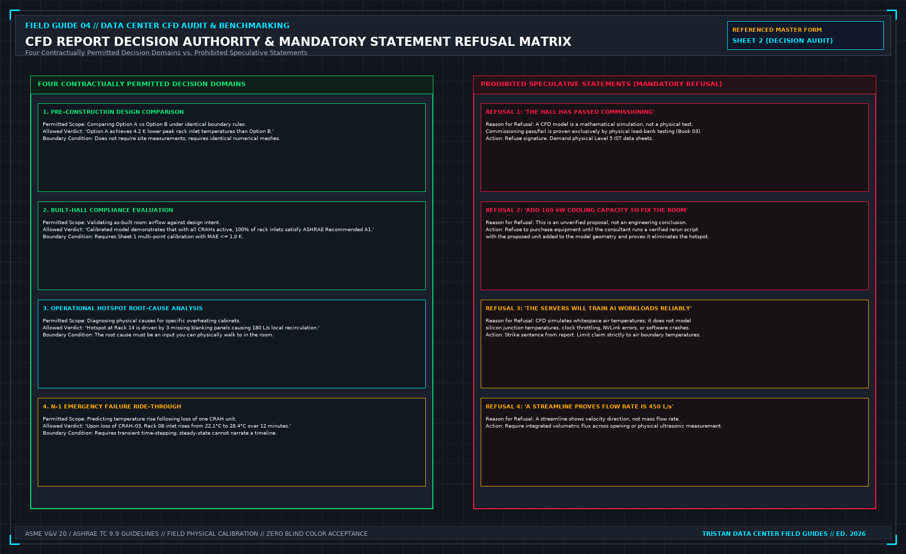
A computational fluid dynamics report that has not been benchmarked against calibrated physical instruments is an artistic opinion rendered in partial differential equations. If an engineering consultant presents a simulation report based entirely on uncalibrated assumptions, that document must be stamped on its cover: "UNVERIFIED DESIGN HYPOTHESIS".
If the report is intended to serve as an operational baseline for an existing, physical data hall, physical field benchmarking must precede any interpretation of the results.
The Minimal Field Benchmarking Grid
Do not attempt to deploy hundreds of temporary thermocouples in an undisciplined mesh across the whitespace. An unorganized cloud of sensor readings creates confusion rather than calibration. The standard benchmarking protocol focuses on high-precision data capture at critical fluid boundaries:
1. Cooling Unit (CRAH / In-Row / Fan Wall) Openings
- Supply Air Discharge: Measure air temperature at the discharge opening using calibrated fast-response thermistors or PT100 probes. You must average at least two distinct points across the discharge plane (S_1, S_2). Taking a casual reading with a handheld thermometer standing two meters out in the aisle is unacceptable; room air entrainment cools or warms the air stream before it reaches the floor, distorting the unit's true thermodynamic discharge.
- Return Air Grille: Measure air temperature across the return grille using at least three distinct points (R_1, R_2, R_3) distributed across the top, center, and bottom of the intake face. Return grilles frequently exhibit thermal stratification of 3.0 K to 6.0 K between their lower and upper edges. A single sensor taped to the center of the grille produces a misleading return temperature value.
2. Cabinet Intake and Exhaust Profiles
At every cabinet position designated in the project claim (or every high-density load-bank rack footprint), measure air temperature along a standardized vertical intake tree:
- Bottom Intake (T_1): 0.3 m above finished floor (approximately rack unit U06). Evaluates floor jet entrainment and underfloor tile plume delivery.
- Middle Intake (T_2): 1.2 m above finished floor (approximately rack unit U24). Serves as the core reference intake temperature for the server chassis array.
- Top Intake (T_3): 1.8 m above finished floor (approximately rack unit U42). Evaluates hot air recirculation rolling over the top of the cabinet or escaping containment roof joints.
In uncontained or partially contained rows, T_3 is frequently 5.0 K to 10.0 K hotter than T_1. Averaging all three points into a single "cabinet temperature" obscures localized thermal stress. Each vertical elevation must be recorded independently on Sheet 1.
3. Exhaust Discharge Face
Measure exhaust temperature at the rear perforated door at the same three vertical elevations. The local delta-T across the server chassis (ΔT_rack = T_exhaust - T_intake) provides the empirical boundary condition needed to verify internal server fan mass flow rates:
The Electrical Nameplate Fallacy
Thermal heat input into the CFD model must be sourced directly from active electrical feed telemetry, never from manufacturer nameplate ratings.
The power rating stamped on a server power supply unit (e.g., 1600 W PSU on a 2U chassis) represents an electrical safety maximum, sizing the branch circuit conductors and overcurrent protective devices. Under actual production compute workloads, that chassis may consume only 650 W to 850 W; an idle server may draw less than 250 W.
THE NAMEPLATE INFLATION TRAP
| EQUIPMENT CLASS | NAMEPLATE RATING (kW) | ACTIVE MEASURED (kW) | MODEL OVERESTIMATION |
|---|---|---|---|
| High-Density AI Rack Enterprise Server Rack Core Network Spine Rack | 160.0 kW (PSU Sum) 14.5 kW (PSU Sum) 22.0 kW (PSU Sum) | 120.0 kW (Active PDU) 8.2 kW (Active PDU) 11.4 kW (Active PDU) | + 33.3% False Heat + 76.8% False Heat + 93.0% False Heat |
If a CFD modeler inputs server nameplate ratings into their software, the model injects 40% to 80% more thermal energy into the simulated whitespace than physically exists. The simulation will predict widespread thermal throttling, red hot spots, and cooling plant failure.
The data center operator will then be urged to spend capital adding unnecessary CRAH units or lowering chilled water setpoints. Always read active 3-phase kW from the PDU smart meter or revenue-grade branch circuit monitor on the day of testing, and verify that this number is the heat source term assigned to that rack in the simulation software.
Spatial Alignment of Numerical Probes
Every measurement point logged on Sheet 1 must correspond to an identical numerical sampling probe within the CFD solver's computational domain.
A numerical probe placed in the center of the cold aisle in software cannot be compared against a physical thermocouple taped to a server front bezel. Air velocity and temperature gradients in the boundary layer immediately adjacent to the perforated door are steep.
If the numerical probe coordinates do not match the physical coordinates within ± 50 mm, the delta between simulation and reality is a spatial sampling error, not a model defect.
Date Synchronization and Layout Freezes
Record the calendar date and shift timestamp of the physical field measurements alongside the geometry freeze date of the CAD model.
Data centers are dynamic environments. Over the course of three months, facility technicians install blanking panels, re-route underfloor power cables, adjust CRAH fan speed setpoints, and add floor grilles.
If your temperature measurements were taken in November on an as-built layout, and the CFD consultant ran their model using an architectural schematic from the previous February, the model does not represent the room you measured. The report must state which layout revision is modeled; an undocumented mixture of dates invalidates the calibration.
Pneumatic Airflow Metrology and Uncertainty Budgets
Temperature measurements alone cannot constrain a data hall CFD model because temperature is a ratio of thermal power to mass flow rate (Δ T = Q / (ṁ cp)). If a simulation underpredicts both rack power and airflow by 35%, the simulated temperature rise Δ T will accidentally match the field temperature while the underlying velocity field and recirculation plumes are completely wrong. Therefore, Sheet 1 requires simultaneous pneumatic airflow and differential pressure measurements alongside the 3-tier thermometry grid.
Capture-Hood Balometer Protocol for Perforated Floor Tiles
To establish the true supply boundary condition from a raised-floor plenum, volumetric airflow (Qtile) must be measured across a representative sample of perforated floor tiles (minimum every third tile along each cold aisle, plus both end-of-row tiles adjacent to high-pressure or high-velocity zones):
Where:
- Cd is the empirical discharge coefficient of the perforated grille and damper assembly (typically 0.60 to 0.78).
- Afree is the net open perforated area of the 600 mm × 600 mm tile (m2).
- Δ Pplenum = Psubfloor - Paisle is the local static pressure differential across the tile (Pa).
- ρair is the local air density (≈ 1.18 kg/m3 at 24^\circC sea level).
When placing a capture-hood balometer over a perforated floor tile, the hood skirt itself introduces a parasitic backpressure resistance (Δ Phood). In low-pressure plenums (Δ Pplenum < 12 Pa) or on high-open-area grates (> 50% open area), an uncompensated hood chokes the tile jet and under-reads true volumetric flow by 10% to 18%. Always use a powered zero-pressure-drop (backpressure-compensated) balometer or cross-check the capture hood against a 16-point hot-wire anemometer traverse conducted 50 mm above the tile face.
| Field Metrology Instrument | Measured Parameter | Minimum Calibration Class | Mandatory Field Deployment Rule |
|---|---|---|---|
| 4-Wire Pt100 RTD / Thermistor Tree | Rack intake (0.3, 1.2, 1.8 m) & CRAH Tsup/Tret | ± 0.15^\circC (IEC 60751 Class A) | Radiation-shielded tip; 50 mm standoff in front of bezel |
| Backpressure-Compensated Balometer | Perforated floor tile volumetric flow (Qtile) | ± 3.0% of reading ± 12 m3/h | Skirt sealed flush to floor; automatic backpressure compensation active |
| Hot-Wire / Vane Anemometer Grid | CRAH coil face velocity & open cutout jets | ± 2.0% of reading ± 0.03 m/s | Minimum 12-point equal-area traverse across discharge opening |
| Micro-Manometer (Differential Δ P) | Subfloor-to-aisle & cold-to-hot containment Δ P | ± 1.0% of reading ± 0.2 Pa | Static pressure tip oriented perpendicular to local shear flow |
| Revenue-Grade 3-Phase PDU Meter | True active electrical power (Pelec) per rack | IEC 62053-22 Class 0.5S (± 0.5%) | Simultaneous timestamped poll during thermal equilibrium dwell |
Accounting for Hybrid Liquid-Air Heat Splits on High-Density Racks
In halls housing direct-to-chip liquid-cooled racks (such as NVL72 clusters or dense GPU pods), feeding total electrical PDU power (Pelec) into the airspace CFD domain is an immediate fatal error. The sensible heat rejected into the room air (Qair) is strictly the residual after subtracting the enthalpy absorbed by the secondary coolant loop:
For a 120.0 kW rack operating at an 82% liquid capture fraction (Qliquid = 98.4 kW), only 21.6 kW enters the air stream via rear door fans and power shelves. Every hybrid rack on Sheet 1 must record both Pelec and Qliquid so the CFD boundary condition reflects true sensible air heating.
Subfloor Static Pressure Mapping and Bernoulli Venturi Starvation
In raised-floor plenums with shallow slab-to-slab heights (450 mm to 600 mm) and high-capacity perimeter CRAH units, high horizontal air velocity (vplenum > 4.5 m/s) immediately downstream of the CRAH discharge converts static pressure into dynamic velocity head according to Bernoulli's equation along a subfloor streamline:
When dynamic pressure 1 / 2ρ vplenum2 exceeds the static plenum pressure near the first two perforated floor tiles adjacent to a CRAH discharge, the local static gauge pressure Pstatic(x) - Paisle drops near zero or turns negative! Instead of discharging conditioned cold air upward into the cold aisle, those first two perforated tiles either stall (Qtile ≈ 0) or induct warm room air downward into the subfloor plenum (the Venturi reverse-flow effect).
| Distance from CRAH Discharge | Subfloor Horizontal Velocity (vplenum) | Dynamic Pressure Head (1 / 2ρ v2) | Local Static Δ Ptile | Observed Perforated Tile Behavior |
|---|---|---|---|---|
| 0.6 m (Tile 1, Unbaffled) | 6.2 m/s | 22.7 Pa | -2.5 Pa (Negative!) | Reverse suction: warm aisle air pulled into floor |
| 1.8 m (Tile 3, Transition) | 4.1 m/s | 9.9 Pa | +8.4 Pa | Severe under-delivery (310 CFM vs 750 CFM target) |
| 4.8 m (Tile 8, Mid-Row) | 1.8 m/s | 1.9 Pa | +18.5 Pa | Nominal balanced delivery (760 CFM) |
| 9.6 m (Tile 16, Dead-End) | 0.4 m/s | 0.1 Pa | +21.2 Pa (Static regain) | Over-delivery (840 CFM) unless damped |
Standard coarse-grid CFD models that represent the entire raised floor as a uniform constant-pressure boundary completely miss Bernoulli static-pressure recovery and Venturi tile reversal. Sheet 1 therefore requires measuring static Δ Ptile at the first tile, mid-row tile, and last tile of every cold aisle.
Pitot-Static Traverse and Coil Enthalpy Cross-Checks on Perimeter CRAH Units
When a CRAH unit's internal BMS supply-air sensor or fan-speed flow estimate is suspected of drift, the field benchmarking team verifies total unit volumetric airflow (QCRAH) against the waterside chilled-water enthalpy balance across the cooling coil:
Under sensible-only dry-coil operation (when TCHW, supply > Tdp, hall), the airside mass flow rate must agree with the waterside heat balance within ± 6.0%. Any larger discrepancy proves either scaled ultrasonic water flow meters or severe air-velocity maldistribution across the discharge plenum.
| CRAH Cross-Check Parameter | Waterside Measurement Method | Airside Measurement Method | Maximum Allowable Discrepancy |
|---|---|---|---|
| Sensible Heat Duty (QCRAH) | Ultrasonic flowmeter ṁCHW + paired immersion RTDs | 16-point velocity traverse × ρ cp (Tret - Tsup) | ≤ ± 6.0% at steady state |
| Supply Air Temperature (Tsup) | Verified above coil leaving water temp (TCHW, in + Δ Tapp) | Arithmetic mean of S1, S2 discharge plane RTDs | ≤ ± 0.4 K vs BMS point |
| Return Air Temperature (Tret) | Verified below coil leaving water limit | Area-weighted mean of R1, R2, R3 intake grille RTDs | ≤ ± 0.5 K vs BMS point |
3. Field Verification Checklist and Instrumentation Hygiene
To execute this protocol without introducing measurement bias or scope ambiguity, the responsible engineer enforces four mandatory field rules:
- Instrument Traceability Before Observation: Verify that every thermometer (4-wire Pt100 RTD Class A), pressure transducer (≤ ± 0.1% span), flowmeter, balometer, or power analyzer carries a current calibration certificate and passes a pre-test zero/span check on the day of the walk.
- Synchronized Time-Series Capture: Align all digital loggers and gateway pollers to a single UTC reference clock (via IEEE 1588v2 PTP at ± 1 ms for electrical Sequence of Events, or NTP at ± 10 ms for thermal/hydraulic dwells). Never merge unsynchronized CSV files by row index.
- Explicit Isolation of Disturbances vs. Control Handles: Hold upstream supply temperatures, parallel cabinet loads, and containment door states constant during the observation dwell so that transient plant drift is never mistaken for steady-state equipment performance.
- Written Record Prior to Signature: Record every boundary tag, measured value, uncertainty tolerance, and open limitation in ink on the controlled project sheet before leaving the equipment line-up.
Frequently Asked Questions (FAQ)
Why does "A missing floor tile is a supply leak" matter during high-density data center commissioning and operations?
Quantifying subfloor static pressure loss and CFM bypass through unsealed raised-floor cable cutouts and missing perforated tiles in data halls. When project teams bypass this rule to meet a commercial schedule milestone, unverified physical assumptions—such as hidden hydraulic pressure drops, unlogged polling gaps, unblanked bypass leakage, or uncalibrated sensor offsets—transfer directly into live 24/7 production as latent single points of failure.
How do you quantitatively verify compliance with "raised floor cable cutout air leakage calculation" on the physical floor?
Compliance is verified by executing the governing mathematical balance (Qcutout = Cd · Acutout · √(2 Δ Pplenum / ρair)) using independent, calibrated field instruments across a stabilized steady-state dwell window (minimum 15 to 30 minutes for thermal and hydraulic systems), and confirming that the discrepancy between primary and secondary measurements remains strictly within the pre-declared acceptance band.
What should an engineer do if a contractor or vendor submits a report that violates this protocol?
The reviewing engineer must refuse to sign the broad acceptance sentence, mark the specific line item as Unproved / Defective on the official audit sheet, and either require a witnessed re-test under a corrected script or isolate the unproved scope under a time-bounded Conditional Acceptance with a 150% to 200% financial retainage escrow holdback.
From Judge a CFD Model for Data Centers, Tristan, Data Center Field Guides.
Related: A CFD picture is not a measurement.
Master the Complete Protocol: Judge a CFD Model for Data Centers
Whitespace Aerodynamics, Containment Leakage, Tile Velocity, and Field Validation
Stop relying on contractor spreadsheets and vendor marketing claims. This field guide provides the complete, auditable verification binder—including physical equations, inspection stations, acceptance thresholds, and signed refusal templates.