 DATA CENTER
Liquid Cooling Commissioning: CDU Testing Checklist (L1–L5)
DIRECT ANSWER & VERIFICATION THRESHOLD:Liquid cooling commissioning is the sequential L1–L5 verification of the Facility Water System (FWS, primary), the Coolant Distribution Unit (CDU) heat-exchange boundary, and the Technology Cooling System (TCS, secondary) before connecting live GPU racks. Commissioning authorities enforce three hard gates: isolate and bypass the CDU plate heat exchanger (
PHE-101) and micro-filters during L3 flush-and-fill until fluid velocity (≥ 1.5 m/s) and cleanliness pass; verify L4 CDU testing including pump discharge check valves, cold no-heat pump curves, and N+1 failover; and prove L5 enthalpy closure (97.0%--101.5%) using calibrated liquid load banks.
Plugging a multi-million-dollar direct-to-chip AI rack into an un-flushed or unverified liquid cooling loop turns construction mill scale and trapped air into immediate microchannel blockage. Standard air-side HVAC commissioning cannot detect secondary hydraulic starvation, check-valve back-spin, or glycol thermal capacitance errors inside a closed liquid plant.
This checklist structures CDU commissioning and testing strictly across data center commissioning levels 1 to 5, defining the physical loop boundaries, first-principles sizing checks, non-negotiable hold points, and handover baselines required before IT hardware lands on the floor.
1. Loop Boundary and Coupled CDU Heat-Balance Physics
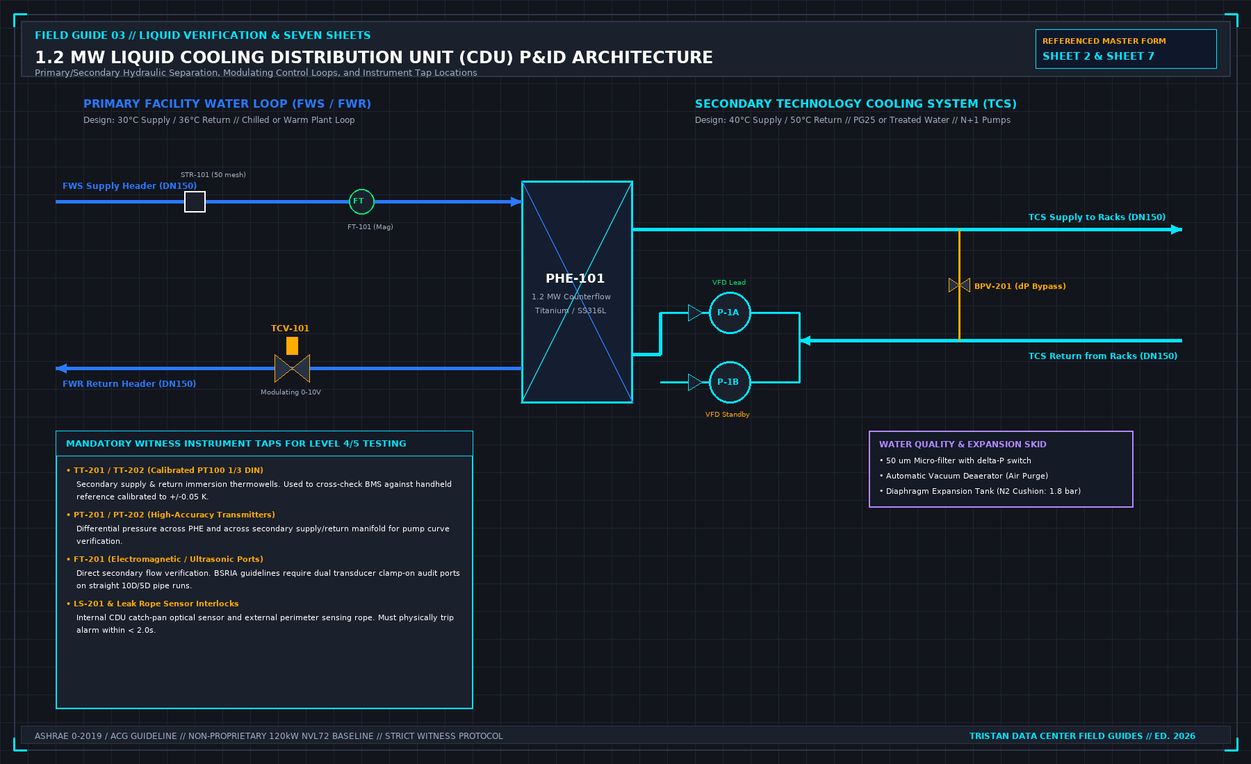
Every liquid cooling test plan begins by splitting two physically separate loops across the CDU titanium or 316L stainless plate heat exchanger (PHE-101):
- Primary Loop — Facility Water System (FWS / FWR): Chilled or facility warm water supplied from the central plant (chillers, dry coolers, or cooling towers) through a 50-mesh strainer (
STR-101), electromagnetic flow meter (FT-101), and modulating 0–10 V temperature control valve (TCV-101). - Secondary Loop — Technology Cooling System (TCS): Treated deionized water or inhibited 25% propylene glycol (
PG25) circulating via redundantN+1VFD pumps (P-1A / P-1B) through a 50 μm filter skid, vacuum deaerator, nitrogen-cushioned expansion tank, differential-pressure bypass valve (BPV-201), and rack manifolds.
Remember that a liquid load bank is not a CDU: the CDU is the cooling plant that conditions the secondary fluid, whereas the load bank acts solely as the rack-side thermal and hydraulic sink during testing.
Governing Heat-Balance and Approach Equations
At steady-state thermal dwell during Level 5 testing, heat absorbed by the TCS loop must reconcile across the plate heat exchanger against heat rejected into the FWS loop, while maintaining design Approach Temperature Difference (Δ Tapproach):
Worked Reference Verification (1.2 MW CDU Baseline)
Using the reference design envelope in Figure 1 (QCDU = 1,200 kW):
- Secondary TCS Loop (PG25 at 45°C mean): TTCS,sup = 40.0°C, TTCS,ret = 50.0°C (Δ TTCS = 10.0 K), cp,PG25 = 3.95 kJ/(kg·K), ρPG25 = 1,018 kg/m3.
- Primary FWS Loop (Treated Water at 33°C mean): TFWS,sup = 30.0°C, TFWS,ret = 36.0°C (Δ TFWS = 6.0 K), cp,FWS = 4.180 kJ/(kg·K), ρFWS = 994.7 kg/m3.
Computing the mandatory steady-state flow rates and heat-exchanger approach yields:
If measured FT-201 secondary flow and TT-201/TT-202 RTD enthalpy yield a heat balance ratio QTCS / Pelec outside 97.0%--101.5%, or if Δ Tapproach drifts upward under full load, suspect either BPV-201 bypass leakage, air-bound PHE-101 plates, or an uncalibrated flow meter.
2. L3 Flush-and-Fill Physics and Check Valve Verification
Two mechanical failure modes routinely wreck liquid cooling commissioning before thermal testing even starts: insufficient flushing velocity and faulty pump discharge check valves.
Why Nominal Pump Flow Can Fail L3 Flush Velocity
Per BSRIA BG 29 flushing practice, dynamic flushing must sweep construction debris out of horizontal runs at velocity vflush ≥ 1.5 m/s:
For a Schedule 40S DN150 header (Di = 154.1 mm, A = 186.5 cm2), reaching 1.5 m/s requires 100.7 m3/h (1,679 L/min). A DN200 main trunk (Di = 202.7 mm) requires 174.3 m3/h (2,904 L/min). Notice the trap: running a single 50%-capacity CDU pump (53.7 m3/h) across an un-zoned DN150 header yields only 0.80 m/s—slow enough for heavy welding slag and gasket fragments to stay parked on the pipe invert until live pumps accelerate later. Always isolate branch headers and connect a dedicated high-head flushing pump across a temporary bypass spool that excludes PHE-101 and the 50 μm filter housings.
Check Valves for CDU Pumps (P-1A / P-1B Non-Return Gate)
Every redundant N+1 CDU pump discharge requires a fast-seating spring-assisted silent check valve (never a slow gravity swing check on high-head variable-speed headers). During L4 changeover testing:
- Back-Spin Bypass Risk: If the standby pump's check valve hangs slightly ajar due to installation debris, the lead pump drives reverse flow backward through the idle pump volute. Header Δ P collapses even though both pump VFDs report healthy amps.
- Water Hammer Slam: Under the Joukowsky relation (Δ Psurge = ρ · c · Δ v), a sluggish swing check valve that lets reverse velocity reach Δ v = 1.5 m/s before slamming shut in a water/PG25 steel line (c ≈ 1,200 m/s, ρ = 1,018 kg/m3) generates an instantaneous theoretical surge spike exceeding 1,832 kPa (18.3 bar)—capable of unseating manifold quick disconnects or rupturing expansion bladders. Silent spring check valves must seat prior to flow reversal, capping measured transient pressure spikes within ± 50 kPa.
3. Printable L1–L5 CDU Commissioning Checklist
Execute each stage strictly in order using pre-approved, version-controlled test scripts. No stage may open while Category A defects remain open in the preceding level.
| Level | Phase & Scope | Mandatory Verification Check | Quantitative Acceptance Gate |
|---|---|---|---|
| L1 | Factory Acceptance (FAT) | Hydrostatic shell test on CDU piping and PHE-101; pump head-flow stand test; factory TCV-101 stroke check | Zero pressure decay at 1.5× WP; pump curve within ± 5% of submittal; ISO 17025 sensor certs attached |
| L2 | Site Receipt & Static QA | Shock-watch inspection; flange torque & seismic anchor checks; VFD/IGBT/SPD-isolated Megger insulation test | Zero shipping impact trips; ground continuity ≤ 0.1 Ω; Rinsul ≥ 100 MΩ at 1,000 VDC |
| L3 | Flush, Hydro Hold & Fill | Bypass PHE-101 & 50 μm filters; flush all zones; hydrostatic hold; vacuum deaeration; PG25 charge & N2 cushion | Flush velocity ≥ 1.5 m/s; turbidity < 5 NTU; 1.5× WP hold 2 h zero decay; PG25 25.0% ± 0.5% |
| L4 | CDU Functional (FPT) | Cold no-heat pump curve (VFD locked); N+1 pump trip & check valve test; TCV-101 Class IV seat leak; hardware alarm injection | Standby start ≤ 500 ms; Δ P recovery ≤ 1.5 s; check surge ≤ ± 50 kPa; leak rope trip < 2.0 s |
| L5 | Integrated Testing (IST) | Stepped liquid load bank ladder (25/50/75/100/110%); manifold balance; 2N feeder loss; FWS loss ride-through | QTCS / Pelec ∈ [97.0%, 101.5%]; row flow CV ≤ 5.0%; TTCS,sup - Tdew ≥ 2.0 K; EOP shunt-trip ≤ 2.0 s |
4. Detailed Field Execution Steps (L3 through L6)
Phase A: L3 Loop Conditioning and Chemistry Sign-Off
- Install Temporary Flushing Spools: Physically isolate
PHE-101,TCV-101, and the CDU 50 μm filter housings with blind spools before connecting temporary flush pumps. - Dynamic Flush & Side-Stream Filtration: Circulate treated water at ≥ 1.5 m/s per isolated branch until return water passes < 5 NTU turbidity, differential pressure across clean 50 μm bag filters stabilizes, and dissolved iron/suspended solids meet project water-quality specs. Never leave untreated stagnant flush water in carbon-steel or mixed-metal piping past 24 hours.
- Hydrostatic Hold & Deaeration: Reconnect the CDU, hold 1.5× working pressure for 2 hours, verify the nitrogen bladder pre-charge on the expansion tank (e.g., 1.8 bar per design sheet), charge inhibited PG25 via refractometer check (25.0% ± 0.5%), and run the automatic vacuum deaerator until zero micro-bubbles appear in sight glasses.
Phase B: L4 Standalone CDU Functional Testing
Execute standalone verification per our one liquid system at a time protocol before applying heat:
- Cold No-Heat Pump Curve: Lock VFD control out of auto-Δ P mode and log head vs. flow across four manual valve throttle positions (
100% / 80% / 60% / 40%) at constant fluid temperature (± 0.5 K). - N+1 Pump Changeover & Check Valve Audit: Trip lead pump
P-1Aat 100% flow. ConfirmP-1Bcommand in ≤ 500 ms, full header Δ P restoration in ≤ 1.5 s, zero reverse shaft spin onP-1A, and check-valve surge ≤ ± 50 kPa. - Point-to-Point Telemetry & Hardware Alarms: Cross-check
TT-201/202,PT-201/202, andFT-201against handheld NIST-traceable references, then physically trip low-flow, expansion-tank level, and leak-detection ropes (`< 2.0 s$). Do not accept bit-forced software alarms; require physical witnessed verification.
Phase C: L5 Integrated Testing with Liquid Load Banks & Handover (L6)
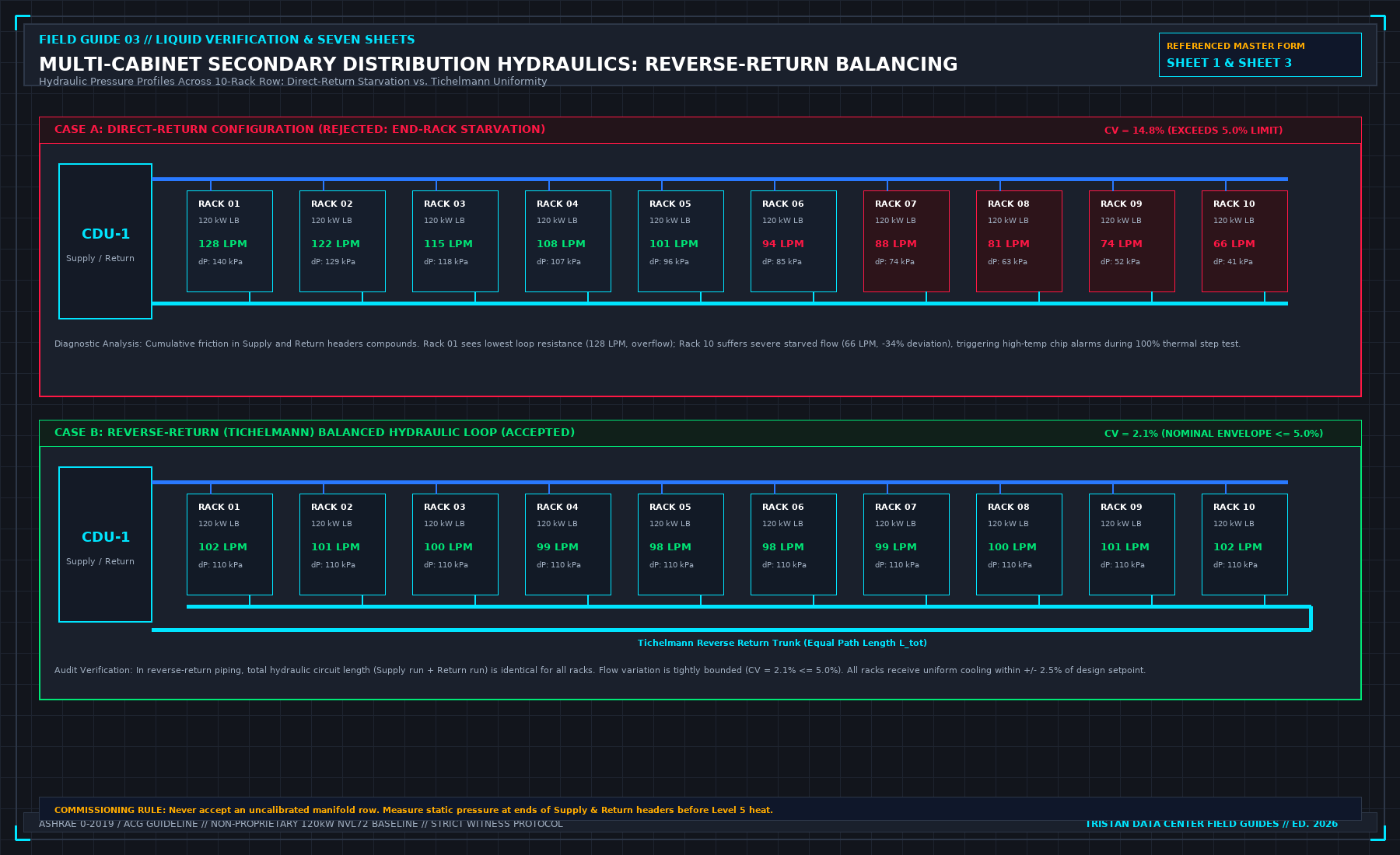
- Row Manifold Flow Balance: Using calibrated rack-side load banks or flow-balancing valves, measure branch flow across all cabinets (
Rack 01toRack N) as shown in Figure 2. Reject direct-return header designs exhibiting end-rack starvation (coefficient of variation CV > 5.0%); demand Tichelmann reverse-return uniformity (CV ≤ 5.0%). - Thermal Step Ladder & Dew-Point Guard: Ramp load banks across
25%,50%,75%,100%(4-hour soak), and110%overload. ConfirmTT-201supply stability (± 0.5 K), enthalpy closure within 97.0%--101.5%, and secondary supply temperature continuously ≥ 2.0 K above room dew point to prevent manifold condensation. - 2N Power Pull & 5-Second EOP Interlocks: Execute A-feed/B-feed UPS transfer tests and validate the hardwired zero-flow shunt-trip within ≤ 2.0 seconds, matching liquid cooling EOP design limits.
- L6 Baseline Archiving: Before handover, archive the signed 7 master sheets, cold vs. hot pump curves,
TCV-101PID gains, verified total fluid volume, and SHA-256 checksummed 1-second CSV telemetry trends into the closeout binder.
Frequently Asked Questions (FAQ)
What is the difference between the FWS loop and TCS loop in liquid cooling commissioning?
The Facility Water System (FWS) is the primary building cooling loop (chilled water or cooling-tower/dry-cooler water) feeding the outside of the CDU plate heat exchanger. The Technology Cooling System (TCS) is the closed, finely filtered secondary loop (treated water or PG25 glycol) circulating between the CDU and the IT rack manifolds. Commissioning must test and isolate both loops separately across PHE-101.
Why must the CDU plate heat exchanger be bypassed during liquid cooling flush and fill?
Plate heat exchangers (PHE-101) have narrow, corrugated internal channels only a few millimeters wide designed to maximize turbulence. Flushing raw piping through the CDU forces weld slag, pipe dope, and construction grit directly into those channels and the 50 μm filter basket, causing permanent fouling and false pressure drop during L4 and L5 testing.
What check valve failures occur during CDU N+1 pump commissioning?
The two most common defects are debris-wedged non-return seats (allowing the running pump to push coolant backward through the idle pump instead of out to the racks) and slow-closing swing check valves (generating severe Joukowsky water-hammer pressure spikes during rapid N+1 changeover). Spring-assisted silent check valves must be physically verified for zero back-spin and pressure spikes within ± 50 kPa.
Can air load banks be used instead of liquid load banks for Level 5 CDU commissioning?
No. Floor-standing resistive air heaters only warm the room air and leave the secondary TCS liquid loop cold and unpressurized under zero thermal Δ T. Level 5 CDU verification requires liquid-cooled load banks that replicate both rack hydraulic impedance (Δ P) and direct thermal dissipation (Q) into the secondary coolant stream.
The Book Bridge
This checklist covers the end-to-end L1–L5 CDU verification sequence. The complete contractor-facing test binder—including the seven printable witness sheets, P&ID boundary drawings, 1-second flash-report pass formulas, and formal refusal clauses—is published across Tristan's Data Center Field Guides series: