 DATA CENTER
The 5-Second EOP: Designing Emergency Operating Procedures for NVL72 and High-Density Liquid Cooling
DIRECT ANSWER & VERIFICATION THRESHOLD:In high-density AI data centers, an Emergency Operating Procedure (EOP) is a reflexive fault-containment script designed to isolate catastrophic hazards and transition the plant into the First Safe State. While legacy air-cooled rooms provide 3 to 10 minutes of room-air thermal inertia during a cooling trip, a 120 kW NVIDIA GB200 NVL72 liquid-cooled rack reaches cold-plate microchannel boiling and thermal runaway in 4.5 seconds upon complete loss of flow. Consequently, high-density liquid cooling EOPs cannot rely on manual binder reading; they must combine hardware-interlocked EPO/throttling reflexes (<2 s) with deterministic technician containment steps.
A laminated binder on the control room wall cannot outrun 120 kilowatts of trapped silicon heat. By the time a technician hears a horn, stands up, and walks to the rack aisle, a dry cold plate has already boiled.
In legacy 5 kW to 10 kW air-cooled enterprise data halls, an Emergency Operating Procedure (EOP) was designed around human walking speed. When a computer room air handler (CRAH) tripped, the shift technician had minutes of physical margin: enter the whitespace, inspect the supply damper, check the chilled-water actuator, and radio the chief engineer. Thousands of cubic meters of cold-aisle and subfloor plenum air buffered the heat load.
In a high-density AI hall operating 120 kW to 135 kW liquid-cooled racks, that human reaction window has vanished.
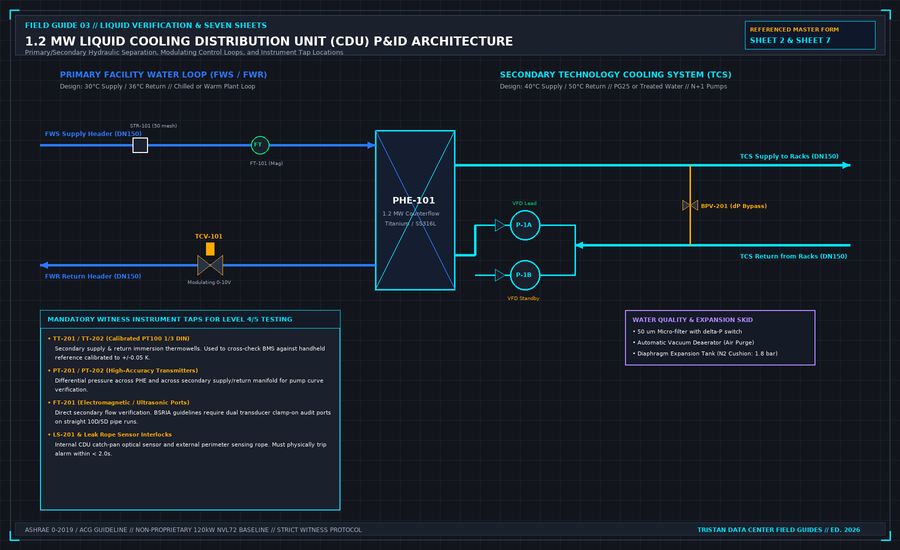
As established in our foundational protocol on why a liquid load bank is not a CDU, direct-to-chip cold plates capture 85% to 90% of the total rack electrical draw and transfer it into a thin film of 25% Propylene Glycol (PG25) flowing through microchannels with hydraulic diameters under 250 μm. If a secondary CDU pump cavitates, a header motorized valve slams shut, or a quick-disconnect (QD) coupling unseats, stagnant fluid inside the cold plates stops convecting heat out to the rack manifold.
If your facility EOP assumes a technician will hear an alarm, walk to the rack row, and read a 12-page flowchart before cutting compute power, your accelerators have already hit thermal shutdown or suffered permanent package warping.
1. First-Principles Thermodynamics of the 5-Second Ride-Through Limit
A common engineering error during data center design reviews is calculating liquid cooling thermal ride-through using the entire fluid volume of the secondary piping loop (35 L to 50 L per rack share). That calculation is physically invalid during a loss-of-flow event (ṁ → 0).
When circulation stops, the fluid standing in the vertical rack manifolds and overhead distribution piping is thermally decoupled from the silicon dies. For an NVIDIA GB200 NVL72 class rack operating at Prack = 135 kW total electrical power with an 88.9% liquid capture ratio (ηcapture = 0.889, where 15 kW is rejected to room air via chassis fans and Qliquid = 120 kW = 120 kJ/s enters the cold plates), the only thermal mass absorbing that 120 kJ/s heat flux is the resident fluid trapped directly inside the cold-plate microchannels (mch) and the active copper cold-plate base mass (mCu) across the 72 GPUs and 36 CPUs:
Substituting representative reference parameters for a 120 kW liquid-captured direct-to-chip rack operating on an ASHRAE W40 supply envelope (note: exact masses and setpoints must always be parameterized from OEM cold-plate thermal capacitance sheets and actual loop static pressure):
- mch = 1.85 kg (Resident PG25 fluid inventory inside active cold-plate microchannel fin stacks).
- cp,PG25 = 3.85 kJ/(kg·K) (Specific heat capacity of 25% propylene glycol at 50°C).
- Tfluid,0 = 55°C (Mean boundary-layer fluid temperature under full 120 kW liquid load) to Tsat = 105°C (Local nucleate film-boiling onset for PG25 at ∼ 1.15--1.20 bar(a) post-pump-trip static manifold pressure).
- mCu = 14.0 kg (Active OFHC copper cold-plate baseplate mass thermally coupled to the dies).
- cp,Cu = 0.385 kJ/(kg·K) from TCu,0 = 60°C to Tthrottle = 95°C (Hardware thermal trip threshold).
Evaluating the numerator energy buffers directly yields the true physical time-to-criticality:
Within 4.54 seconds of complete flow stoppage, vapor blanketing (Critical Heat Flux dryout) forms inside the microchannels, driving thermal resistance upward and spiking local vapor pressure across elastomer O-rings.
2. Two-Stage EOP Architecture: Hardware Reflex + Human Stabilization
Because no human operator can diagnose an alarm and flip a breaker within 4.54 seconds, an auditable data center EOP for high-density liquid cooling must be split into two sequential stages:
- Stage 1 (0.0 s to 2.0 s — Deterministic Hardware Interlock): Hardwired safety relays and BMC protection cut heat input and isolate fluid momentum automatically, with zero reliance on software polling loops.
- Stage 2 (2.0 s to 300 s — Technician First-Safe-State Protocol): The on-duty technician executes a 4-step physical verification walk to lock the zone in the First Safe State and hand off to an authorized MOP.
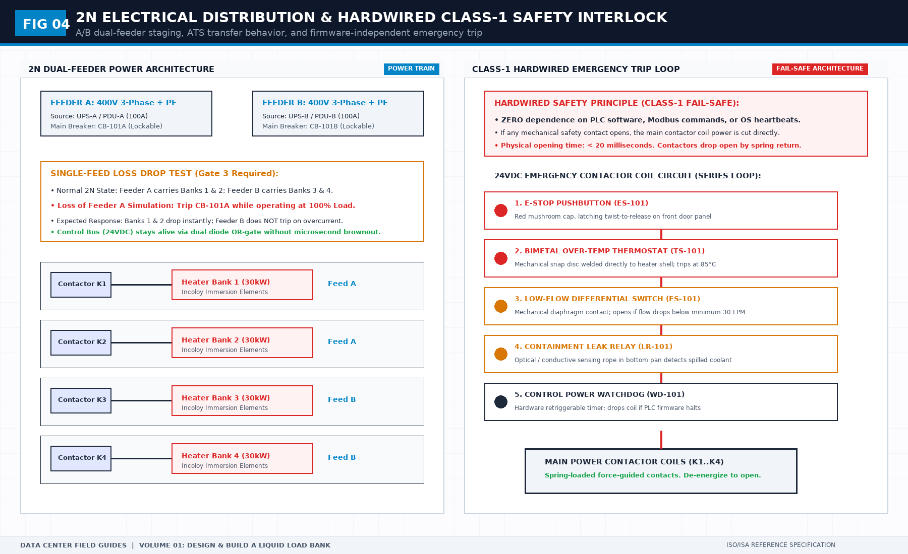
Engineering Note on Figure 04 Interlock Architecture: In our reference load-bank and rack safety chain, "Class-1 Hardwired Fail-Safe" denotes a project-defined series 24 VDC hardware trip circuit (
ES-101E-Stop,TS-10185°C bimetal thermostat,FS-101low-flow switch,LR-101leak rope relay,WD-101watchdog) that bypasses PLC software. Note the distinction between mechanical contactor contact parting time (<20 ms spring-return dropout once the 24 VDC coil circuit opens) and total end-to-end fault clearance time (tdetect + tactuate ≤ 2.0 s, which includes sensor hydraulic/thermal response plus breaker or valve stroke). Reference thresholds (85°C, 30 L/min) must be calibrated to the specific rack's minimum flow-per-kilowatt safety curve.
| Emergency Fault Scenario | Stage 1 Hardware Trigger (<2.0 s) | Automated Interlock Action | Stage 2 Technician First Safe State (<5 min) |
|---|---|---|---|
| EOP-LC-01: Catastrophic Secondary Manifold Leak | Differential pressure drop dP / dt > 0.8 bar/s OR dual under-rack rope leak sensors wet | Trip CDU secondary pumps; close motorized zone isolation valves MIV-S1/R1; open rack power shelf shunt-trip | Verify rack zero-energy state; deploy PG25 spill containment dikes; lock out CDU zone breaker |
| EOP-LC-02: Complete Loss of Secondary Flow | Dual ultrasonic/mag flowmeters report V̇ < 15 L/min for >500 ms | Assert hardware PROCHOT# brake via rack BMC; if flow remains <15 L/min at t = 2.0 s, trip rack PDU breakers | Confirm compute trays powered down; check CDU expansion tank sight glass and pump seal integrity |
| EOP-LC-03: Primary Chilled-Water Loss to CDU | CDU secondary supply Tsup > 48°C OR primary Δ P < 15 kPa | Ramp secondary pumps to 100% to maximize loop thermal mixing; issue graceful workload shed signal; trip IT load at Tsup = 52°C | Verify companion rear-door heat exchanger (RDHx) airflow active; hold secondary circulation until Tret < 35°C |
| EOP-LC-04: Expansion Tank Loss of Bladder Pressure | Expansion tank pressure Pexp < 0.5 bar(g) (Pump NPSH cavitation risk) | Inhibit standby pump auto-start to prevent dry mechanical seal destruction; initiate controlled compute load shed | Isolate expansion vessel manual service valve; check relief valve discharge line before any refill MOP |
3. Four Fatal Defects in Legacy Liquid Cooling EOPs
When auditing hyperscale and colocation liquid cooling procedures against our SOP/MOP/EOP RACI Authorization Matrix, four dangerous procedural anti-patterns require immediate rejection:
- Directing Technicians to "Locate the Leak" Before Isolating Power:
- The Defect: EOP step 1 instructs the technician to "Enter the hot aisle and visually inspect rack manifolds to identify the leaking quick-disconnect."
- The Physics: At 2.5 bar operating pressure, a sheared QD or split EPDM hose sprays conductive 55°C glycol-water mist across 48 VDC busbars and 415 VAC power shelves. Entering the aisle before zone isolation and electrical shunt-trip is a severe life-safety hazard.
- Forcing Standby Pump Start on Low Suction Pressure:
- The Defect: Treating a CDU pump trip like an air-handler fan trip by manually forcing the redundant pump to 100% speed.
- The Physics: If Pump A tripped on low suction pressure due to a ruptured hose or collapsed expansion bladder, starting Pump B pumps the remaining loop inventory onto the data hall floor while destroying Pump B's silicon-carbide mechanical seal via vapor cavitation.
- Trapping Hot Fluid Inside Isolated Cold Plates:
- The Defect: Slamming rack manifold isolation valves shut on a primary cooling loss while compute trays are still coasting down.
- The Physics: If there is no leak in the secondary loop, secondary pumps must keep circulating fluid through the cold plates for 180 seconds after IT power trip to absorb residual die and package heat (Tjunction → Tloop) and prevent localized boiling pressure spikes.
- Refilling or Bleeding Loops Inside the EOP:
- The Defect: Including steps to hook up a make-up cart and bleed air inside the emergency document.
- The Physics: An EOP stops at the First Safe State. Introducing un-deaerated fluid or opening bleed ports under emergency stress injects micro-bubbles that cause immediate hot-spot dryout upon restart. Refilling and vacuum-bleeding require a formal, witnessed MOP.
4. Field Commissioning Verification Checklist for Liquid EOPs
During Level 4 (L4) and Level 5 (L5) Integrated Systems Testing (IST), the commissioning authority must physically prove the 5-second EOP interlocks using a calibrated liquid load bank before live GPUs are installed:
- Simulated Zero-Flow Shunt-Trip Timing Test:
- With the rack liquid load bank operating at 120 kW steady-state thermal load, command the secondary zone isolation valve closed.
- Measure the exact elapsed time from flow drop (V̇ < 15 L/min or project-calibrated
FS-101trip point) to load-bank contactor dropout using an IEEE 1588v2 PTP-synchronized (≤ 1.0 μs) or NTP Stratum-1 (≤ 1.0 ms) power quality analyzer and SOE recorder. - Acceptance Criterion: Hardwired contactor coil dropout in < 20 ms after flow-switch opening; total end-to-end power interruption achieved in ≤ 2.00 seconds; peak cold-plate simulator surface temperature stays ≤ 85°C.
- Leak-Rope to Motorized Valve Closure Stroke Test:
- Apply 50 mL of PG25 test fluid to the drip-tray optical/conductive sensor.
- Acceptance Criterion: CDU secondary pumps trip within ≤ 1.0 second; motorized isolation valves reach 100% seated closure within ≤ 4.0 seconds.
- Physical EOP Placard Verification at the CDU:
- Verify that laminated, single-page EOP placards (
EOP-LC-01throughEOP-LC-04) are physically mounted on every CDU door and row-end EPO station, displaying exact valve tag IDs (CDU-04-MIV-S1) and breaker numbers.
5. Frequently Asked Questions (FAQ)
What is the meaning of EOP in a data center and when does it terminate?
EOP stands for Emergency Operating Procedure. It is a short, pre-authorized action script executed immediately during an uncontained facility emergency (such as a cooling loop rupture, electrical arc-fault, or utility blackout). An EOP terminates the exact moment the facility reaches the First Safe State—where human life is protected and surviving equipment is stabilized. All subsequent diagnostics, repairs, and restarts must be executed under a separate Method of Procedure (MOP).
Why do NVL72 liquid-cooled racks require a 5-second EOP response?
Unlike air-cooled servers that can draw on thousands of cubic meters of room air for several minutes during a cooling failure, a 120 kW liquid-cooled rack holds only ∼ 1.85 kg of coolant inside its active cold-plate microchannels. When flow stops, that trapped fluid absorbs 120 kJ/s of heat and reaches film-boiling temperature in approximately 4.54 seconds, requiring automated hardware power-cut interlocks under 2.0 seconds.
Should technicians shut off secondary CDU pumps during a primary chilled-water failure?
No. If the secondary loop is intact (zero leaks) and only the primary chilled-water supply has failed, secondary CDU pumps must continue running while compute load is shed or tripped. Continuing secondary circulation distributes residual silicon heat across the entire secondary pipe loop mass, preventing localized boiling inside the cold plates.
6. Field Reference & Authoritative Standard Citations
- ASHRAE TC 9.9 (2021): Water-Cooled Servers: Common Designs, Components, and Processes (Supply water classes W17–W45, leak containment, and fault ride-through).
- Open Compute Project (OCP) — Advanced Cooling Solutions (ACS): Cold Plate and CDU Specification (Quick-disconnect spillage limits and secondary loop interlock requirements).
- NFPA 70 (NEC) Article 645: Information Technology Equipment (Emergency Power Off disconnecting means and liquid cooling electrical clearance).
This protocol governs high-density liquid cooling emergency containment. The complete engineering specification—including 120 kW liquid load bank design schematics, Danfoss FD83 quick-disconnect verification gates, and Level 4 IST test scripts—is published in Volume 01: Design and Build a Liquid Load Bank for NVL72 Racks by Tristan.
>
Explore Volume 01 Details | Order on Amazon Kindle & Leanpub →