 DATA CENTER
The MOP Point of No Return: Why Switching Rollbacks Cause Secondary Cascading Outages
DIRECT ANSWER & VERIFICATION THRESHOLD:In mission-critical facility engineering, a Method of Procedure (MOP) is an authorized, step-by-step switching script governing planned maintenance on live electrical, mechanical, or cooling infrastructure. The Point of No Return (PONR) is the exact, pre-calculated step beyond which reversing the sequence (attempting a "rollback" or "back-out") introduces higher electrical, hydraulic, or thermal instability than driving forward to a stable state. Once the PONR is crossed, blind rollbacks are strictly prohibited; any unexpected fault requires immediate transition to an Emergency Operating Procedure (EOP).
A switching order is not a conveyor belt you can run in reverse. Physical power and cooling plants remember every breaker stroke.
At 02:45 AM during an approved maintenance window, a 4,000 A low-voltage main circuit breaker is being racked out after transferring load to the parallel maintenance bypass bus. Halfway between the Connected and Test positions, the racking worm-gear binds. An auxiliary dry contact (52b) fails to report open, and an upstream PLC triggers a bus-tie discrepancy alarm.
In the high-pressure minutes that follow, an unseasoned shift lead makes the classic fatal error: "Abort the maintenance—roll the steps backward and put the load back on Main Breaker A."
Without verifying bus phase angle drift, trapped spring-charging energy, or transformer core remanent flux, the technician commands the bypass breaker open while slamming the primary breaker back in. The resulting out-of-phase closure drives magnetizing inrush above 8 × Irated, trips the upstream 15 kV medium-voltage feeder on instantaneous overcurrent (ANSI Device 50/51), and drops both redundant paths simultaneously.
The original defect was mechanical friction on an isolated breaker carriage. The improvised rollback turned it into a full-facility blackout.
1. The Physics of the Rollback Trap
Software engineers can execute git revert because digital state transitions are massless. Physical power and cooling plants possess electromagnetic inertia, trapped fluid momentum, and thermal capacitance.
As detailed in our foundational protocol on why a MOP must exist before tools arrive, reversing an invasive switching sequence mid-stream exposes live equipment to three physical failure mechanisms:
A. Transformer Core Remanent Flux and Inrush Saturation
When a power transformer is de-energized during an MOP step and hastily re-energized during an aborted rollback at an arbitrary voltage zero-crossing angle θ, residual magnetic flux (Φres) trapped in the core adds constructively to the applied AC flux wave:
Under worst-case zero-crossing closure (θ = 0, evaluated at the first half-cycle peak ω t = π where e-t/τ ≈ 1), total core flux reaches Φpeak ≈ 2 Φmax + Φres. Once core flux exceeds the magnetic saturation knee (Φsat), winding inductance collapses to saturated air-core inductance (Lair), driving a peak magnetizing inrush current (in Amperes, Wb/H = A) of:
Where N1 is primary winding turns and Lsys is upstream source inductance. This transient inrush current routinely reaches 6 × Irated to 10 × Irated for the first 50 ms to 200 ms, tripping upstream protective relays that were tightened for N-1 maintenance mode.
B. Out-of-Phase Bus Paralleling Torque
During UPS static bypass transfers or dual-source tie-breaker closures, reversing a transfer after the sync-check relay (Device 25) window has drifted by an angle Δ δ subjects generator shafts and transformer windings to synchronising power surges proportional to the sine of the phase displacement:
C. Hydraulic Joukowsky Water Hammer
In chilled-water and high-density CDU primary loops, aborting an isolation sequence by snapping a motorized butterfly valve back open against a spinning pump column generates a pressure shock wave (Δ Psurge) governed by the Joukowsky water-hammer equation:
In a 400 mm steel chilled-water riser where acoustic wave speed awave ≈ 1,200 m/s, a sudden velocity reversal of Δ v = 1.5 m/s produces an instantaneous pressure spike of Δ Psurge = 1,000 × 1,200 × 1.5 = 1.8 MPa (18 bar), rupturing expansion joints and Victaulic gaskets.
2. Architecture of an Auditable MOP: The Three Switching Zones
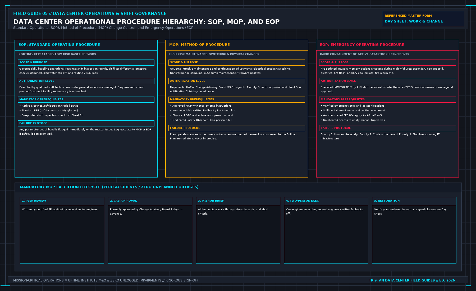
Within the broader SOP vs MOP vs EOP operational governance framework, an auditable MOP is never a linear list of steps with a generic "reverse order to back out" footnote. It is partitioned into three explicit operational zones separated by the Point of No Return (PONR) Gate:
| Switching Zone | Physical Plant State | Permitted Fault Response | Governing Authority & Protocol |
|---|---|---|---|
| Zone 1: Pre-PONR (Safe Abort Corridor) | Pre-checks, instrument hookup, LOTO preparation, sync verification; zero breakers or valves stroked. | Controlled Back-Out Permitted | Execute pre-validated Zone 1 Back-Out steps in exact written sequence to restore baseline. |
| Zone 2: The PONR Boundary Step | The exact physical step that alters load path, opens a primary breaker, or unseats an isolation valve. | Mid-Stroke Abort Forbidden | Hold point immediately prior; once initiated, the actuator or breaker operation must complete its stroke. |
| Zone 3: Post-PONR (Committed State) | Load transferred to alternate path; primary equipment de-energized, grounded, or drained. | Uncalculated Rollback Prohibited | If an active fault occurs, halt the MOP immediately and execute the staged subsystem EOP to lock the First Safe State (or follow a pre-engineered Post-PONR Contingency once sync/equalization preconditions are met). |
Sample Field MOP Switching Ledger (UPS Module Maintenance Isolation)
Every production MOP must format the PONR boundary and the mandatory OSHA 29 CFR 1910.147 / NFPA 70E Lockout/Tagout (Live-Dead-Live) sequence directly inside the step table:
| Step ID | Zone | Action Description | Expected Telemetry / Physical Verification | Operator / Verifier Sign & UTC |
|---|---|---|---|---|
| STEP 04 | Zone 1 | Verify UPS-2A and UPS-2B output phase synchronization on EPMS panel. | Phase difference | Δ δ| ≤ 1.5°; Voltage Δ V ≤ 1.0 V; Load ≤ 42%. | [Op: ____] [Ver: ____] [UTC: ____] |
| STEP 05 | PONR | HOLD POINT — POINT OF NO RETURN: Obtain verbal release from DCO Lead before closing Maintenance Bypass Breaker MBB-2A. | Confirm zero active alarms on redundant Train B (Bus-2B stable at 480 V). | [DCO Release: ____] [UTC: ____] |
| STEP 06 | Zone 2 | Turn Kirk-Key interlock KK-2A and close Maintenance Bypass Breaker MBB-2A. | Physical mechanical flag shows CLOSED (Red); parallel current share verified. | [Op: ____] [Ver: ____] [UTC: ____] |
| STEP 07 | Zone 3 | Open UPS Output Isolation Breaker UOB-2A, rack to DISCONNECTED, and apply personal LOTO padlock #0412 + danger tag. | POST-PONR: Do NOT re-close UOB-2A if alarm sounds; transition to EOP-UPS-02. | [Op: ____] [Ver: ____] [UTC: ____] |
| STEP 08 | Zone 3 | ZERO-ENERGY VERIFICATION (Live-Dead-Live): Test CAT IV 1,000 V meter on known live source, verify 0.0 VAC/VDC across all UOB-2A load terminals & bled DC link, re-verify meter on live source. | L-L and L-G < 1.0 V; DC capacitor bus < 5.0 VDC before opening internal bay doors. | [Op: ____] [Ver: ____] [UTC: ____] |
3. Five Non-Negotiable Field Rules for MOP Execution
As codified in the SOP/MOP/EOP RACI Authorization Matrix, field operations teams must enforce five execution rules during every maintenance window:
- Two-Person Call-and-Response (Operator + Verifier): No invasive MOP step is ever performed solo. The Verifier reads the step number, equipment tag ID, and expected response aloud from the printed binder; the Operator places a gloved finger on the physical nameplate tag, repeats the tag aloud, and waits for the Verifier's "Confirmed—Execute" command.
- Mandatory Pre-PONR Hold and Telemetry Lock: Upon reaching the PONR banner, switching halts for a minimum 120 second dwell. The Verifier confirms with the BMS/EPMS control room that surviving redundant paths carry zero trouble alarms and that 1 s high-speed fault recording is active.
- Zero Jumper Wires or Defeated Interlocks: If a Kirk-key cylinder binds, a motorized breaker refuses to charge, or a PLC permissive fails to clear in Zone 1, technicians are strictly forbidden from using jumper wires, manual cheater bars, or relay blocks. Execute the Zone 1 Back-Out and quarantine the equipment.
- Instant MOP Termination Upon Redundancy Loss: If an unplanned trip or environmental excursion occurs after crossing the PONR, the MOP document is immediately stamped TERMINATED AT STEP [X]. Operators do not improvise reverse steps; they open the staged Emergency Operating Procedure (EOP) (or hardware-interlocked 5-Second Liquid Cooling EOP for NVL72 racks) and stabilize the First Safe State.
- Thermal Discharge and Isolated Dielectric Verification Before Re-Energization: Equipment isolated under an MOP cannot be re-energized until mandatory discharge dwell times (tdischarge ≥ 10 min for DC capacitor banks) and insulation resistance checks (e.g., ≥ 100 MΩ at 1,000 VDC for 480 V buswork per ANSI/NETA MTS, performed only after physically disconnecting all solid-state IGBT bridges, surge protective devices, and control PT fuses) are logged in ink.
4. Pre-Window Audit Refusal Gates
When auditing a contractor-submitted or vendor-authored MOP prior to change-board approval, the reviewing Critical Facility Engineer must reject the document if any of the following four defects appear:
| Audit Defect | Why It Causes Outages | Mandatory Engineering Correction |
|---|---|---|
| "Reverse Above Steps to Back Out" | Assumes physical switching is symmetrically reversible without checking sync, flux, or pressure differentials. | Require a dedicated, step-by-step Zone 1 Back-Out Script with explicit gauge and voltage checks at every step. |
| Missing PONR Declaration | Leaves the floor technician guessing whether it is safer to abort or push forward during a mid-window fault. | Insert a bold, boxed POINT OF NO RETURN hold gate immediately prior to the primary state-change step. |
| Generic Equipment Naming | Uses vague labels like "Open the chiller valve" or "Trip the main breaker" instead of stamped P&ID/SLD tags. | Replace every action with exact physical nameplate tags (e.g., CHW-MOV-04B, SWG-1A-52M). |
| Bundled Multi-System Switching | Combines Train A and Train B maintenance inside a single continuous MOP document. | Split into completely independent MOPs separated by a full steady-state verification dwell. |
5. Frequently Asked Questions (FAQ)
What does MOP stand for in a data center and when is it required?
MOP stands for Method of Procedure. It is required for any planned maintenance, testing, or switching operation that alters electrical, mechanical, cooling, or fire-protection plant topology (Δ S ≠ 0) or temporarily reduces system redundancy from 2N / N+1 to N.
What is the Point of No Return (PONR) in a data center MOP?
The Point of No Return (PONR) is the specific, pre-designated step in a Method of Procedure where physical state transition begins (such as operating a load-break switch, transferring a UPS static bypass, or unseating a header isolation valve). Prior to the PONR, operators can safely abort using the Zone 1 Back-Out plan; past the PONR, reversing steps is prohibited and any fault triggers a direct handoff to an EOP.
Why do MOP rollbacks cause secondary outages in critical facilities?
Attempting an uncalculated rollback after crossing the PONR exposes live equipment to severe transient stresses—including out-of-phase bus closures, transformer core saturation inrush currents (6× to 10× rated current), and hydraulic water hammer—which routinely trip upstream protective breakers on the surviving redundant path.
6. Field Reference & Authoritative Standard Citations
- IEEE Std 3007.1-2010: Recommended Practice for the Operation and Management of Industrial and Commercial Power Systems (Switching order management and back-out boundaries).
- NFPA 70B-2023: Standard for Electrical Equipment Maintenance (Mandatory written switching procedures and pre-task verification).
- OSHA 29 CFR 1910.147: The Control of Hazardous Energy (Lockout/Tagout) (Energy isolation and verification before maintenance execution).
This protocol governs switching boundary discipline and PONR architecture. The complete operational manual—including full switching order templates, pre-window walkdown sheets, and shift manager refusal gates—is published in Volume 05: Run the Data Center Day by Tristan.
>
Explore Volume 05 Details | Order on Amazon Kindle & Leanpub →